2 disc ridger, 3 depth wheels – Great Plains P13937 User Manual
Page 15
15
Series 1 Toolbar
Operating Instructions
Adjustment / Operation
A
B
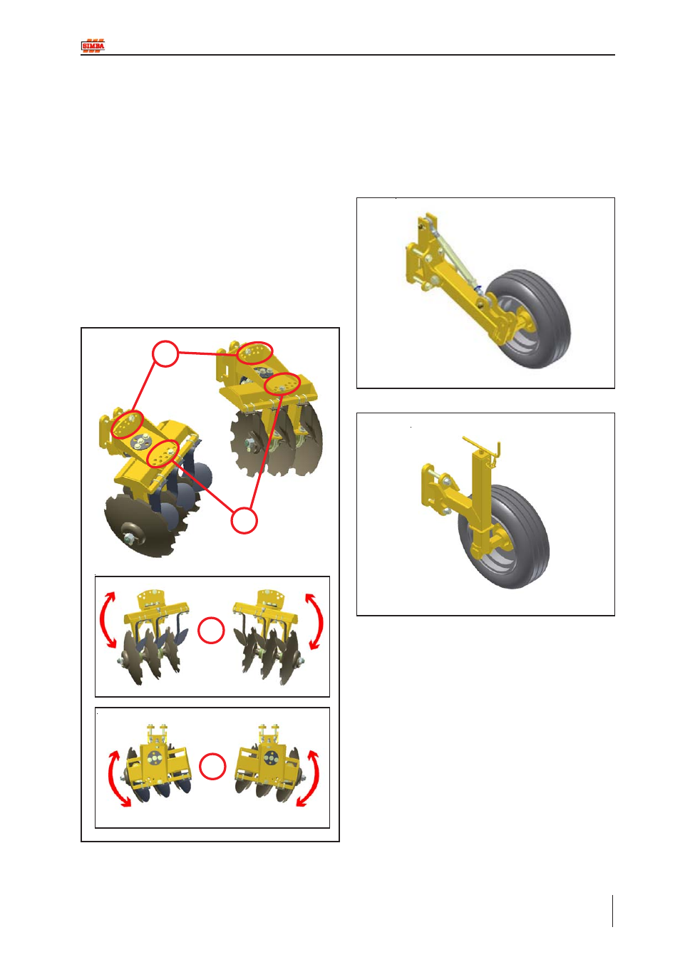
3.2.2 Disc Ridger
Disc ridgers are designed to leave a ridge in
the soil. The disc ridger units are usually
mounted onto the frame in pairs about row
centres however are not limited to this
configuration.
The rotation and angle of the disc ridger units
are altered using bolts positioned in the holes
located at points A and B in the diagram
below. Increasing the rotation (A) will
increase the ridge height. Increasing the disc
angle (B) will increase the cutting and lifting
effect on the soil.
A
B
3.2.3 Depth Wheels
Two different types of depth wheels are
available to regulate the depth of the machine
in work. These wheels are adjusted using
either a toplink adjuster or a jack (depending
on which units are fitted).
Fig. 3.07: Disc Ridger Adjustment
Fig. 3.08: Depth Wheel (Toplink Adjuster Type)
Fig. 3.09: Depth Wheel (Jack Type)
- 1200 Parts Manual (210 pages)
- 706NT Material Rate (46 pages)
- 706NT Material Rate (50 pages)
- 2N-2410 Operator Manual (56 pages)
- 2N-2410 Operator Manual (48 pages)
- 12 Series Drills Assembly Instructions (6 pages)
- X-PresS 2006 Assembly Instructions (50 pages)
- TM500 Operator Manual (62 pages)
- 2010HDP Operator Manual (166 pages)
- YP1630F Material Rate (42 pages)
- YP2425 Operator Manual (162 pages)
- 3S-5000 Operator Manual (94 pages)
- 3PYP Operator Manual (188 pages)
- 3N-3010P Assembly Instructions (2 pages)
- 3N-3010 Assembly Instructions (9 pages)
- 3N-3010P Assembly Instructions (9 pages)
- PFH-15 Predelivery Manual (23 pages)
- PFH-15 Operator Manual (46 pages)
- PFH-15 Operator Manual (26 pages)
- P15126 Serial No 12724 (34 pages)
- DVN 8321 Operator Manual (38 pages)
- 3P500 Assembly Instructions (22 pages)
- 605NT Assembly Instructions (4 pages)
- 3P600 Assembly Instructions (12 pages)
- 605NT Assembly Instructions (8 pages)
- CPH-12 Assembly Instructions (3 pages)
- YP1625A-2420 24 Row 20-Inch Quick Start (6 pages)
- 8323 FCF Predelivery Manual (124 pages)
- 3323 DH Parts Manual (114 pages)
- YP3025-1820 25 Series 18 Row 20 Inch Quick Start (5 pages)
- CF500 Operator Manual (38 pages)
- PFH-15 Assembly Instructions (30 pages)
- 3500TM Parts Manual (106 pages)
- 1800TM Parts Manual (158 pages)
- YP2425A-2470 24 Row 70 cm Quick Start (5 pages)
- Simba Culti Press Operator Manual (38 pages)
- RU1999 Parts Manual (58 pages)
- 3N-30P Assembly Instructions (10 pages)
- 2510HDP Operator Manual (180 pages)
- YP1220 Parts Manual (136 pages)
- 3P500 Material Rate (68 pages)
- YP2425-3620 36 Row 20 Inch Quick Start (5 pages)
- 706NT Operator Manual (22 pages)
- 706NT Operator Manual (53 pages)