Feed control assembly (optional) – Wheatheart Galvanized 4 Utility Auger User Manual
Page 15
W
HEATHEART
- G
RAIN
A
UGERS
3. A
SSEMBLY
4" G
ALVANIZED
U
TILITY
3.5. F
EED
C
ONTROL
A
SSEMBLY
(O
PTIONAL
)
30645 R0
15
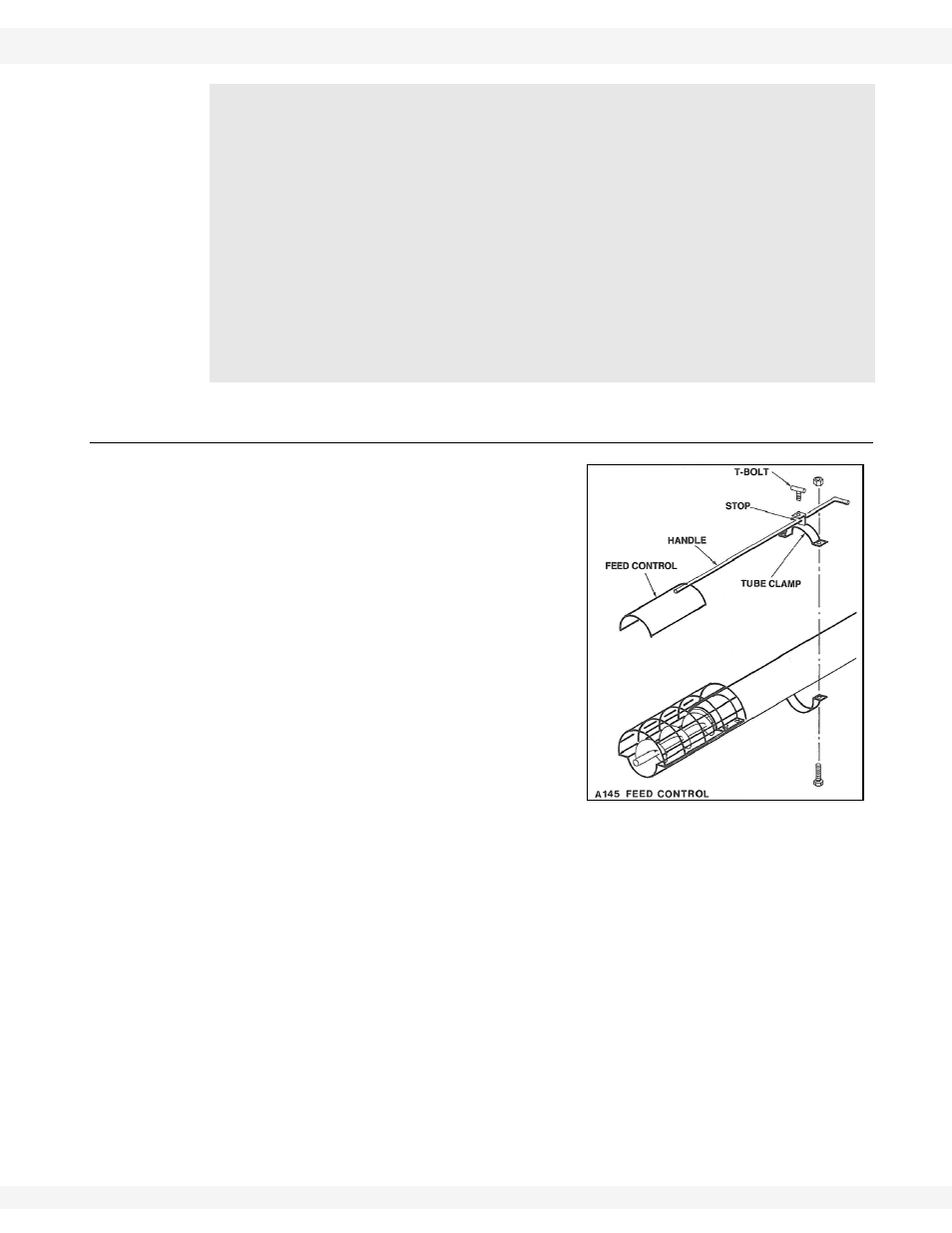
3.5. FEED CONTROL ASSEMBLY (OPTIONAL)
1. Loosely
attach
tube clamp to auger
tube with two 5/16” x 3/4” bolts and
washer-locknuts. Do not tighten at this
time.
2. Thread
the
control handle through tube
clamp as shown, then place feed
control slide beneath the intake guard.
3. Seat
tube
clamp against stop on
control handle and lock into place with
the t -bolt on the clamp.
4. Slide feed control assembly down until
lower end is 1/2” past lower end of
auger tube. Tighten the tube clamp.
When using an electric motor:
• The motor and controls should be installed by a qualified electrician in
accordance with all local and national codes.
• Incorporate a magnetic starter to protect the motor.
• The motor must have a manual reset button.
• Locate reset and starter controls so that the operator has full view of the
entire operation.
• Locate main power disconnect switch within reach from ground level to
permit ready access in case of an emergency.
• A main power disconnect switch capable of being locked (in the off posi-
tion only) must be provided.
Figure 3.6