Warning – Crown Boiler 24-07 User Manual
Page 34
34
of the RTC cannot be used on multiple boiler
installations.
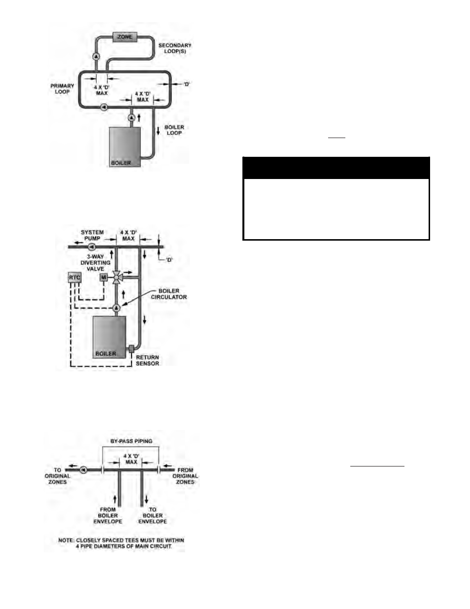
d. Boiler Circulator – The boiler circulator selection
will maintain a constant and minimum flow
through the boiler during every heat demand.
In addition, the circulator will maintain a flow
around the return sensor. The circulator must
be properly selected, based on the design
temperature between the boiler supply and
boiler return. Appendix B lists the appropriate
pumps for both 20 ºF and 40 ºF applications. A
boiler circulator must be used with and without
an RTC System for a primary/secondary piping
arrangement.
WARNING
If the boiler circulator you have selected is
greater than 1/3 HP, an isolation relay must
be added when using the RTC.
If a 3-phase boiler circulator has been
selected than a properly sized motor starter
must be installed when using the RTC.
e. Diverting Valve – A diverting 3-way valve must
be part of the boiler loop for boiler protection to
be active when using the RTC. Only a Crown
approved valve and actuator may be used for
boiler protection. The valve sizing does change
based on the designed boiler ∆T, since the flow
rate and the pressure drop change for each. See
Appendix B for proper valve selection.
f. Glycol Antifreeze Solutions - Many systems
today use ethylene or propylene glycol antifreeze
solutions as a measure for freeze protection, as
well as a pump lubricator and corrosion inhibitor.
The properties of the glycol mixture have an
impact on valve and pump sizing. All glycol
solutions have a lower specific heat than water.
This means that the glycol solution cannot
transfer heat as well as pure water, resulting in
the need for higher flow rates. In addition, the
viscosity of the glycol solution is usually higher
than water, requiring a higher pump head for the
same given flow. Consult factory for specific
applications, pump selection and flow rate.
g. Nipple and Sensor - The 3 x 12 special nipple
must be installed in the lower right return
connection when looking at the rear section,
when using the RTC. Insert the return sensor
using pipe dope.
2. STEAM HEATING, consult I=B=R Installation
and Piping Guide No. 200. For piping details, see
Figure 34. Figure 35 shows a typical pumped return/
boiler feed unit arrangement. Figure 36 illustrates
the required mounting elevations for McDonnell and
Miller 150 and 63 float low water cut-offs.
Figure 28:
Typical Crown Boiler Loop w/3-way Diverting
Valve, Where System Return may be Less than
135°F.
Figure 30: Parallel Piping Conversion
Figure 27:
Typical Crown Boiler - Primary - Secondary Loop
System (Return Temps always Greater than 135°F.)