Power take-off clutches, Mechanical in-line pto (truck flywheel), Allowable side load (lbs.) at 1,800 rpm – Wichita Clutch Mechanical Power Take-Offs User Manual
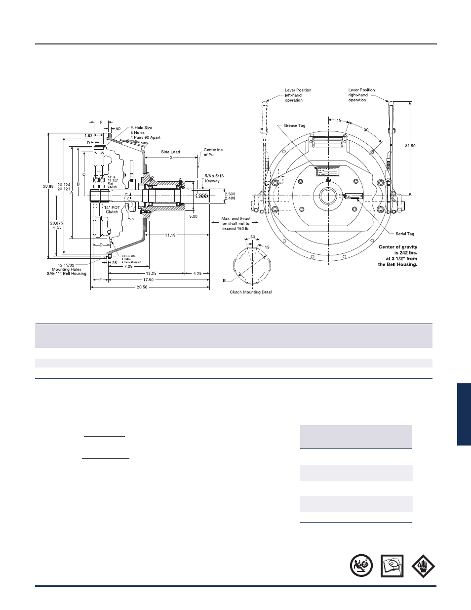
Page 3: Dimensions: inches
F
Power Take-Off Clutches
P-1100-WC 1/12
Wichita Clutch 800-964-3262 147
Estimated Side Load Calculation
#1
L
=
126,000 x HP
x F x SF
N x D
#2
L
=
1,945,000 x kW
x F x SF
N x D
L = Actual Applied Load (lbs. for #1 and kgs for #2)
N = Shaft Speed (RPM)
D = Pitch Diameter (in. for #1 and mm for #2) of Sheave
F = Load Factor
1.0 for Chain Drive or Gear Drive
1.5 for Timing Belts
2.5 for All V-belts
3.5 for All Flat Belts
SF = Service Factor
2.1 for Reciprocating Compressors and other severe shock drives
1.8 for Large Inertia Drives such as Crushers, Chippers, and Planers
Note: It is recommended that the optional support plate be used in side load applications.
Mechanical In-line PTO (Truck Flywheel)
Size 14" Flat, 14" Pot & 15-1/2" Flat
A
Clutch
SAE Bell
Pilot
B
C
E
Size
Housing
(+.000/-.002) in.
Hole Circle
Plate Dia.
D
Hole Size – Qty
F
14" Flat
1
16.50*
15.500
13.56
N/A
13/32
8
2.62
14" Pot
1
14.750
15.500
13.75
2.94
13/32
8
2.50
15-1/2" Flat
1
17.155
16.625
15.22
0.19
15/32
8
2.50
* Nominal diameter only, clutch is not piloted.
Caution: Do not use with Drive Line
Center of gravity is 242 lbs. located 3.50” from bell housing mounting surface
Allowable Side Load (lbs.) at
1,800 RPM
X Side Load
Distance from (lbs.) B
10
Bell Housing Bearing LIfe
3.62 1,600
4.62 1,100
5.62 850
6.62 680
7.62 565
8.62 450
9.62 400
10.26 370
11.25 340
At 2,100 RPM, derate side load by 20%.
Dimensions: inches