Standard vent clutches, Coupling and grinding mill clutches, Selection – Wichita Clutch SV - Standard Ventilated Clutch User Manual
Page 3: Selection example
Standard Vent Clutches
124
Wichita Clutch 800-964-3262
P-1100-WC 1/12
Selection
Clutch sizes are affected by the following
variables:
1. Machines that operate under smooth loads
require smaller clutches. These machines
are driven by either multi-cylinder high
speed engines or electric motors with
reduced starting current.
2. Drives that require high starting current
motors will require clutches with sufficient
torque to prevent excessive slipping while
starting.
3. Starting torque may be high, which
re quires fast clutch response time to
transmit the required torque or extended
clutch slip time to protect the prime mover.
4. Starting torques may be very low
com pared to the normal torque, which
may result in the clutch not being fully
pres sur ized prior to the time of torque
re quire ment. This will cause the clutch
to over-heat from slippage. Clutch inflation
time in this instance is very important.
5. Clutches on most machines are designed
to slip prior to damage from shockloads.
As a result, the clutch may require periodic
maintenance; therefore the clutch should
be located, for easy access, in the power
train. Clutches should also be located for
maximum cooling air. In instances where
this is not possible, forced air cooling may
be nec es sary for extended clutch life.
6. Safe operating speeds for clutches should
be maintained in design. The following
material specifications are rec om mend ed
for safe operation. The max i mum speeds
shown are safe op er at ing speeds based
upon years of Wichita experience.
Maximum Clutch
Contact Velocity FPM Material
6,000
(Recommended upper limit for slip)
cast iron
9,000 ductile iron
12,000 steel
These velocities are measured at the nominal
outside diameter of the clutch plates.
Selection Example
To properly select a clutch for your ap pli ca tion,
the following information is re quired:
1. Application horsepower
2. Re quired air pressure
3. Required torque
4. Clutch heat horsepower
5. Shaft diameter
Chart A (page 123) gives application re quire -
ments ranging from light duty (the A group) to
extra heavy duty (the D group). This chart will
give the initial se lec tion which is then compared
with the selection made using the Clutch Heat
Horsepower Chart B and the Clutch area (see
“lining area” column) in the Spec i fi ca tion Table
(Chart C, page 125-126).
Machine required:
Rock crusher (Grinding mill)
(Group D duty requirement)
WR
2
................................1,000 lb.ft.
2
RPM ..................................1,800
Clutch Slip Time ................6 sec.
HP......................................325 (diesel 8
............................................
cylinder)
Available air pressure ........120 PSI
Clutch must slip while bringing equipment
up to speed.
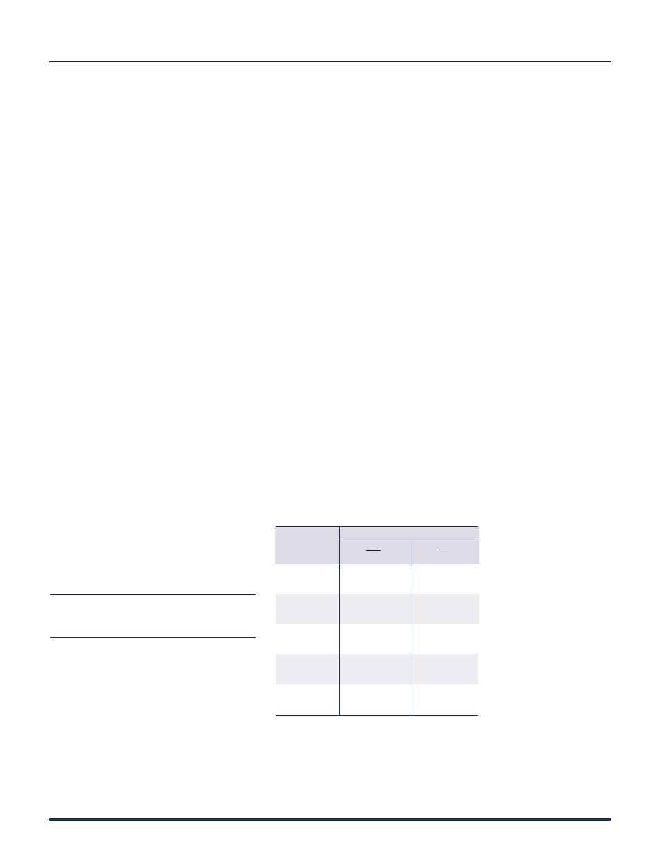
Chart B
Clutch heat horsepower absorption rate*
Slip
Time
Seconds
*
This chart is for use when clutch is at ambient temperature of 120°
F max.
HP
in.
2
ft.lb.
in.
2
Heat Input
Coupling and Grinding Mill Clutches
0 to 1 380 .7
2 617 .56
3 820 .5
4 1,000 .45
5 1,175 .43
6 1,330 .4
7 1,485 .38
8 1,630 .37
9 1,770 .36
10 1,900 .34