Rs-485 option, Valco instruments co. inc. vici ag international, Figure 4: control module, showing jumper locations – VICI Selectors (multiposition) Microelectric User Manual
Page 9: Figure 3: use of the offset feature
®
®
North America, South America, and Australia/Oceania contact:
Europe, Asia, and Africa contact:
Valco Instruments Co. Inc.
VICI AG International
Cheminert
®
and VICI
®
are registered trademarks of Valco Instruments Co. Inc. and VICI AG
P.O. Box 55603
Houston, TX 77255
Sales: (800) 367-8424
Tech: (713) 688-9345
Fax:
(713) 688-8106 [email protected]
Parkstrasse 2
CH-6214 Schenkon
Switzerland
Phone: +41 41 925 6200
Fax:
+41 41 925 6201 [email protected]
TN-415 10/14
JUMPERS 1 AND 2
Figure 4: Control module,
showing jumper locations
the actuator will respond only to move commands for positions “10” through “19”. For any setting of
SO and NP, the lowest valid position will be the SO value and the highest valid position will be the SO
value plus the NP value minus 1; i.e., the actuator will respond to commands for position SO through
position {SO + NP - 1}.
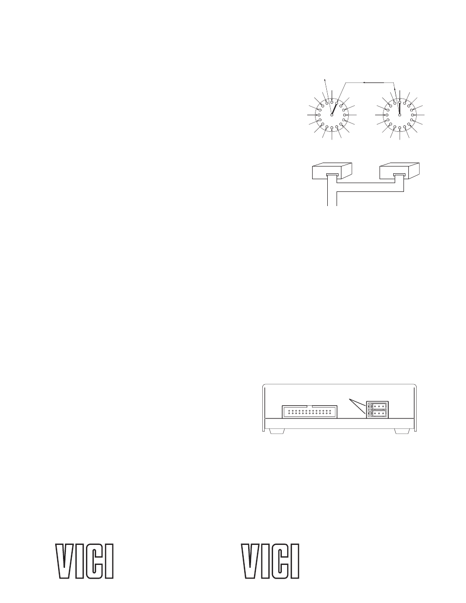
Here is an example of how this can be used to set up a 31-stream
stream selection system using six dedicated BCD lines and two
16-position valves and actuators. First, use the serial port com-
mand “SL1” to enable the auto-latching feature on both actuators.
(This eliminates the need for a data latch signal.) Configure the
second actuator using the serial port command “SO16”, giving it a
valid position range of 16 to 31. Use a piece of tubing to connect
port 16 of the first valve (on the actuator with the SO value still at
the factory setting of “1”) to the common port of the valve on the
second actuator (which now has the SO set to “16”). Connect
streams 1 through 15 to ports 1 through 15 on the first valve, and
streams 16 through 31 to ports 1 through 15 on the second valve.
This system will step sequentially from 1 through 31 with a single
BCD instruction. However, when positions are selected in a random sequence, position 16 must always
be requested before any positions higher 16 are selected.
Figure 3 helps illustrate this: since both
actuators respond to a command to go to position 16, stream 16 will flow through valve 1/port 1, out
the common port of valve 2, into valve 1/port 16, and out of the common port of valve 1. Thereafter,
any stream select command that is above 16 will move only valve 2; when a move command for a
position less than 16 is given, valve 1 will move and cut off all flow from valve 2.
RS-485 Option
Software
The RS-485 option involves three minor software adaptations to the RS-232 protocol. The first is that the
ID range is extended to include the characters “A” through “Z”, with upper and lower cases treated as the
same ID. The second change is that the ID is required (either numbers from 0 to 9 or letters from A to
Z), and must be included in all commands. The factory-set default ID for all devices is “Z”. The third
adaptation is that all commands must include a forward slash [/] as the start-of-message character.
Hardware
The RS-485 hardware includes two 3-pin connectors
(
Figure 4) used as in/out connectors for easy daisy-
chaining of additional devices. Wired in parallel, the
signal assignments are as follows: Pin 1 is Ground,
Pin 2 is Phase B, and Pin 3 is Phase A.
The four male pins in a vertical row to the left of
these connectors are jumper headers, used to add or
remove terminating resistors from the communication lines. The top two and the bottom two should
be jumpered when termination is required. The RS-485 hardware specifications require termina-
tion at each end of the communication line, so in a daisy-chaining application the jumpers should be
removed from all the intermediate devices. The RS-485 port on the host computer or controlling device
generally includes terminating resistors, so only the actuator at the far end of the communication string
needs to have the jumpers installed.
S1
S4
S15
S16
OUTLET
VALVE 1
VALVE 2
CONTROL MODULE
FOR ACTUATOR 1
CONTROL MODULE
FOR ACTUATOR 2
PARALLEL CONTROL LINES
S19
S31
Figure 3: Use of the offset feature