VICI 500 Dynacalibrator User Manual
Page 7
Introduction
Referring again to Figure 1, note that the dilution stream passes through
scrubber #3 and feeds into differential pressure regulator DPR3. The Model 500
contains a dilution flow control valve and rotometer, plus a rotometer for SPAN 1
and SPAN 2 carrier flows. When energized, solenoid control valve SV1 opens to
route carrier 1 flow to the mixing tee. Differential pressure regulator DPR1 main-
tains a fixed 3.2 psi pressure differential across the selected flow control valve
and meter. The flow rate through the selected flowmeter is then a function of this
fixed pressure differential and the carrier flow control orifice FR1. The desired
dilution flow, set using FCV2, is mixed with any selected permeation chamber
output to provide a final output concentration.
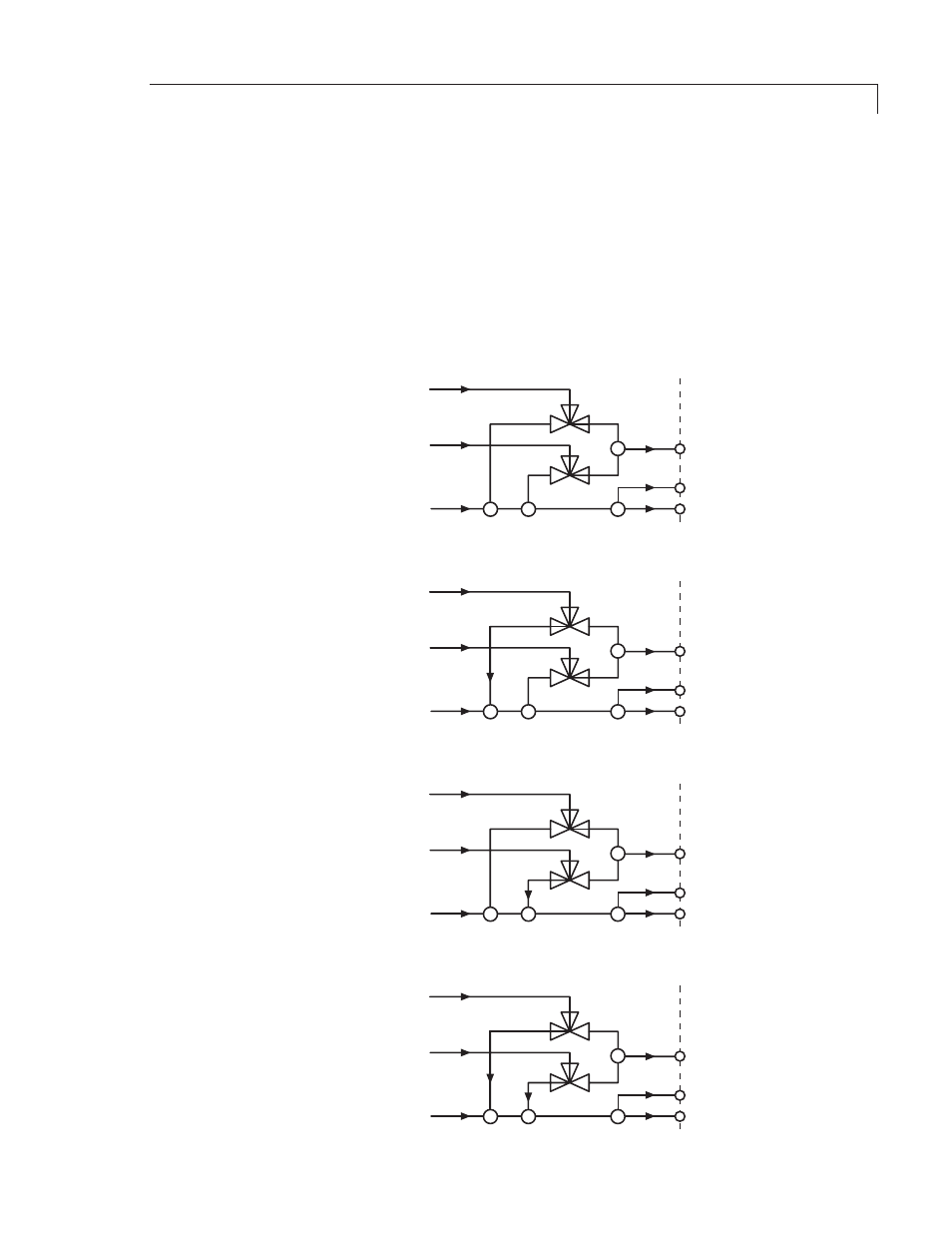
Figure 2: Model 500 output flow configurations
���
��������
����
�������
����
��
��
�
��������
���������
��������
���������������
���
���
���������
��
��
�
���
��������
����
�������
����
��
��
�
��������
���������
��������
������
���
���
���������
��
��
�
���
��������
����
�������
����
��
��
�
��������
���������
��������
������
���
���
���������
��
��
�
���
��������
����
�������
����
��
��
�
��������
���������
��������
���������
���
���
���������
��
��
�