VICI 340 Dynacalibrator User Manual
Page 17
13
DILUTION
FLOW CONTROL
VALVE
MODE
SELECTOR
MODE
INDICATORS
HEATER
CIRCUIT
BREAKER
MAIN
CIRCUIT
BREAKER
HEATER
POWER
SWITCH
HEATER
INDICATOR
MAIN
POWER
INDICATOR
MAIN
POWER
SWITCH
PERMEATION
CHAMBER
CHAMBER
FLOWMETER
TEMPERATURE
EQUILIBRIUM
INDICATOR
TEMPERATURE
DISPLAY
OVEN TEMPERATURE
UPPER LIMIT
DILUTION
FLOWMETER
Metronics Inc.
SHUTDOWN
30°
120°
.15
.10
.05
CHAMBER
FLOW
MODE CONTROL
REMOTE
SPAN
ZERO
DYNACALIBRATOR
MODEL 340
PERMEATION CHAMBER
LOCK
TEMPERATURE °C
PNL TMP
SET
4A
6A
MAIN
HEATER
DILUTION
FLOW
CONTROL
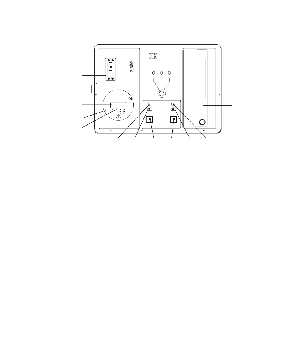
Figure 4: Model 340 front panel controls and indicators
MODE SELECTOR switch and indicators
The three position switch selects the calibration mode. LEDs indicate the current
mode.
• ZERO: The permeation chamber output is dumped out the chamber vent;
only the dilution stream exits through the stream outlet to the analyzer.
• SPAN: The permeation chamber output and the dilution stream are mixed
and fed through the stream outlet to the analyzer.
• REMOTE: Unit defaults to the ZERO mode. A remote contact closure to rear
panel terminals C and V1 will switch the unit to the SPAN mode.
Getting Started