Operation by remote negative true logic, Use of remote leds, Vici ag international – VICI DVI User Manual
Page 3: Valco, Instruments
Operation by Remote Negative True Logic
1. Connect the RED (logic ground) wire from the DVI to the logic ground of the timing device. (Consult
its manual as necessary.)
2. Connect the BLACK (LOAD) wire from the DVI to the output chosen for the LOAD position.
3. Connect the BLUE (INJECT) wire from the DVI to the output chosen for the INJECT position.
Use of Remote LEDs
1.Connect the positive (+) leg of the LEDs to the grey wire of the interface cable.
2. Connect the other legs from the LEDs to the VIOLET wire for the LOAD indicator and to the GREEN
wire for the INJECT indicator.
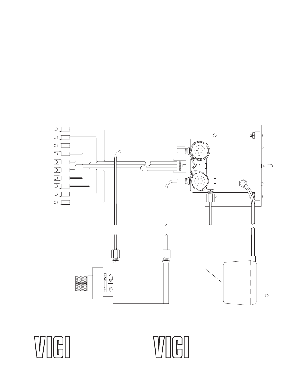
Figure 3: DVI connections
BLACK
WHITE
GREY
VIOLET
BLUE
GREEN
YELLOW
ORANGE
RED
BROWN
INPUT (LOAD)
CONTACT CLOSURE 2
LED DRIVE +
LED 2 (LOAD)
INPUT (INJECT)
LED 1 (INJECT)
CONTACT CLOSURE 1
CONTACT CLOSURE 2
LOGIC GROUND
CONTACT CLOSURE 1
CONNECTION FOR
LOAD POSITION
CONNECTION FOR
INJECT POSITION
AIR IN
(100 psi MAX)
VALCO TWO POSITION
AIR ACTUATOR
DIGITAL VALVE
INTERFACE (DVI)
POWER SUPPLY
TRANSFORMER
ALL INPUTS ARE 5 VOLT NEGATIVE TRUE LOGIC
INPUTS REQUIRE .5 MILLIAMPERES DRIVE
INPUTS MUST HAVE A CLOSURE TO LOGIC GROUND - (RED) TO ACTUATE
1.
2.
3.
NOTE:
TN-411 8/04
VICI AG International
Parkstrasse 2
CH-6214 Schenkon
Switzerland
Phone (Int + 41 + 41) 925-6200
Fax (Int + 41 + 41) 925-6201 [email protected]
Valco
Instruments
Co.
Inc.
P. O. Box 55603
Houston, TX 77255
Sales toll-free (800) 367-8424
Technical help
(713)
688-9345
Fax (713) 688-8106
Cheminert
®
and VICI
®
are registered trademarks of Valco Instruments Co. Inc. and VICI AG
North America, South America, and Australia/Oceania contact:
Europe, Asia, and Africa contact:
®
®