VICI DVI User Manual
Page 2
Basic Connections
1. Connect the air lines between the DVI and the air actuator as shown in Figure 3 on the back page.
2. Connect the air supply line to a regulated source of compressed air or nitrogen. (60-80 psi recom-
mended, 100 psi maximum)
3. Connect the transformer to the DVI as indicated, and plug it in.
Manual Operation
No additional installation is required for use of the three position switch on the front panel of the DVI.
The manual switch will override automatic operation unless the operation is controlled by a single
double throw relay.
Automatic Operation
The DVI can be controlled by one double throw relay, two single throw relays, or remote negative true
logic. The input signals to the DVI can be continuous or as short as fifty milliseconds. Any unused
wires should be taped or tied out of the way.
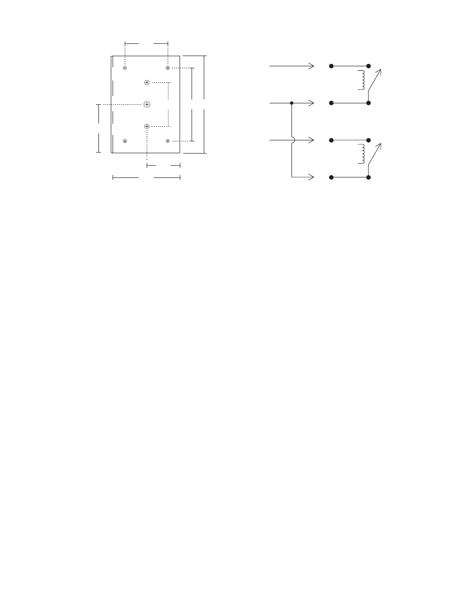
One relay operation (double throw)
1. Connect the BLACK (LOAD) wire from the DVI to the Normally Closed (N.C.) relay contact.
2. Connect the RED (ground) wire to the Common (Com/Grnd) relay contact.
3. Connect the BLUE (INJECT) wire to the Normally Open (N.O.) relay contact.
Two relay operation
1. Connect the RED (ground) wire from the DVI to the common of both relays.
2. Connect the BLACK (LOAD) wire to the Normally Open (N.O.) contact of the relay designated for
the LOAD position.
3. Connect the BLUE (INJECT) wire to the Normally Open (N.O.) contact of the relay designated for
the INJECT position.
LOAD
RELAY
INJECT
RELAY
BLACK
RED
BLUE
Figure 1: Mounting dimensions
1.75”
2”
1.8”
3”
4”
1.35”
2.75”
Figure 2: Relay connections