Assembly – Triton TSP S450 User Manual
Page 6
6
GB
ASSEMBLY
Always ensure that the tool is switched off and
disconnected from the power supply before making
any adjustments or installing or removing spindles.
BENCH MOUNTING
When mounting the spindle sander in a permanent
position ensure that is secured to a rigid work surface.
• Use the holes in the base of the spindle sander as a
template to mark and drill four holes in your intended
mounting surface (ie. workbench). Secure the spindle
sander into position using large bolts, washers and
nuts (not supplied)
• If the spindle sander is intended to be portable, fix a
board to the base which can be easily clamped and
removed from various
mounting surfaces
• Ensure bolts are long
enough to penetrate
the workbench or board
sufficiently for a secure fix
DUST EXTRACTION
It is recommended that the
spindle sander is used with a dust extraction system for a
cleaner and safer work environment.
1. Attach the hose from the dust extraction system to the
Dust Extraction Port (13) and ensure it is secure
2. For greater efficiency, activate the dust extraction
system before turning on the spindle sander
SELECTING A TABLE INSERT
Failure to use the correct table insert with its matching
sanding sleeve could result in pinched fingers or the
workpiece being pulled down between the table insert and
the sanding sleeve.
Use the below chart as a guide to choosing table inserts
and sanding sleeves.
The sanding sleeve should fit snugly into the central
cutout of the table insert.
FITTING A SANDING SLEEVE
Note: All of the sanding sleeves, except the smallest
13mm (
1
⁄
2
") sanding sleeve fit over a matching Rubber
Drum (12).
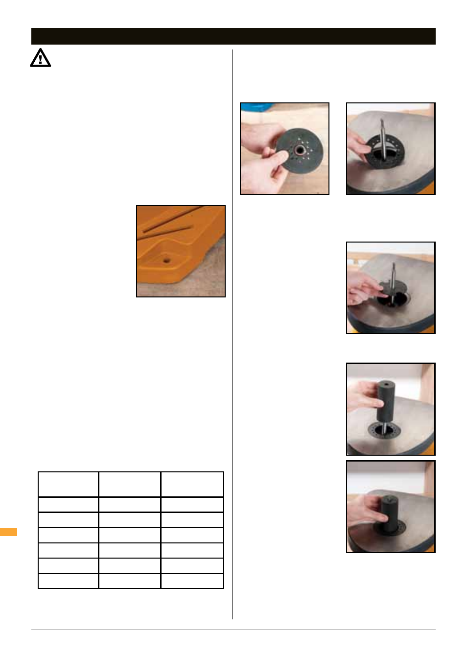
1. Fit the lower Spindle Washer
(7) over the Spindle (5) with
the fin side facing down
2. Select the correct Sanding
Sleeve (11) for the
intended job. Select the
corresponding Rubber Drum
(12), (except when using the
13mm sanding sleeve)
Do not use a sanding drum with the 13mm (
1
⁄
2
") sanding
sleeve.
3. Select the appropriate Table
Insert (10) in accordance
with table above (see
'SELECTING A TABLE
INSERT')
4. Fit the Table Insert (10) over
the Spindle (5) and onto
the lower spindle washer.
Ensure the table insert is
flush with the table
5. Fit the Rubber Drum (12)
over the spindle
6. Slide the Sanding Sleeve (11)
over the Rubber Drum (12)
7. Fit the upper Spindle Washer
(9) over the Spindle (5)
• Use the large washer with
75mm (3"), 51mm (2"), and
38mm (1
1
⁄
2
") rubber drums.
• Use the medium washer with 26mm (1") and 19mm
(
3
⁄
4
") rubber drums
Sanding Sleeve
Dia
Table Insert
Size
Upper Spindle
Washer Size
13mm (
1
⁄
2
")
13mm (
1
⁄
2
")
Small
19mm (
3
⁄
4
")
19mm (
3
⁄
4
")
Medium
26mm (1")
26mm (1")
Medium
38mm (1
1
⁄
2
")
38mm (1
1
⁄
2
")
Large
51mm (2")
51mm (2")
Large
76mm (3")
76mm (3")
Large
Assembly