4 screw-in tool for, 5 pressure/temperature diagram, 2 safety – Richter GU/F Series Overflow Valves User Manual
Page 5: Screw-in tool for, Pressure/temperature diagram, 2safety, Series gu/f
Series GU/F
Page 5
9530-070-en
Revision 00
TM 6908
Edition 10/2007
1.4 Screw-in tool for
Nom. size
[mm]
[inch]
Article-No.
25
1“ ---
40 1½“
9568-96-1012
50, 65
2“ 9568-96-1016
80 3“
9538-96-1002
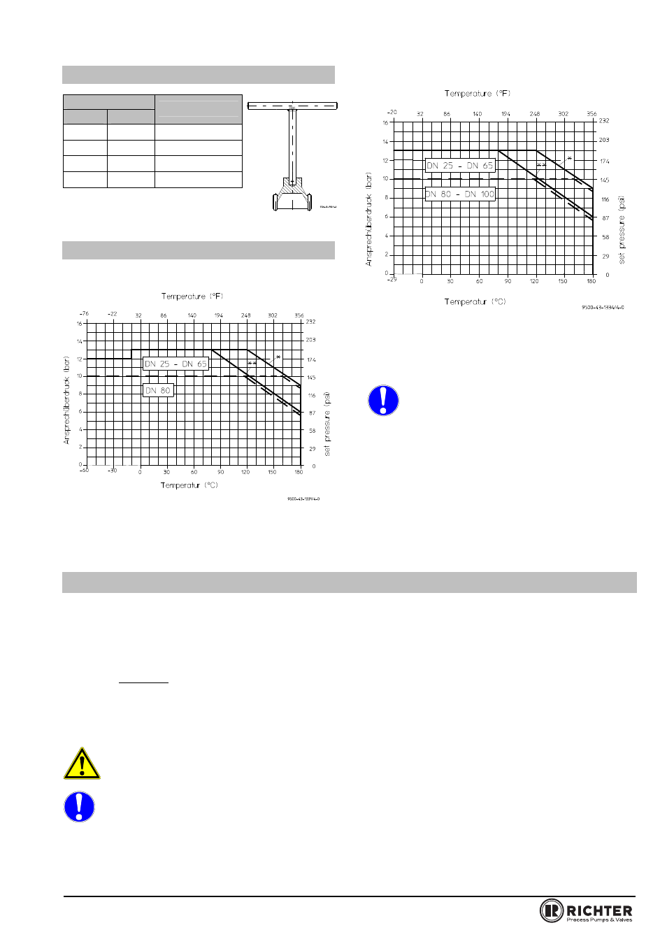
1.5 Pressure/temperature
diagram
According to AD 2000
*
metal seat
** seat/plug PTFE carbon
According to ASME B 16.42
*
metal seat
** seat/plug PTFE carbon
The diagram shows the max. admissible pressure /
temperature loading of the body.
When used in the minus temperature range,
the regulations applicable in the country in
question must be observed.
For applications under -10 °C (14 °F) to -60 °C (-
76 °F) a special material must be selected for the
thrust flange and spindle.
For applications in the range covered by ASME or
ASME/ISA the lowest temperature of ASTM A395 is
limited to -20 °F (-29 °C).
2
Safety
This operating manual contains fundamental
information which is to be observed during installation,
operation and maintenance. It must therefore be
read before installation and commissioning.
For valves which are used in potentially explosive
areas, see Section 3.
Installation and operation are to be performed by
qualified staff.
The area of responsibility, authority and supervision of
the staff must be regulated by the customer.
General hazard symbol !
Peoples may be put at risk.
Safety symbol ! The valve and its function
may be put at risk if this safety symbol is not
observed..
It is imperative to observe warnings and signs
attached directly to the valve and they are to be kept
fully legible.
Non-observance of the notes on safety may result
in the loss of any and all claims for damages.
For example, non-observance may involve the
following hazards:
Failure of important functions of the valve/plant.
Risk to people from electric, mechanical and
chemical effects.
Risk to the environment through leaks of
hazardous substances.