3 end position adjustments, 4 end position adjustments for standard actuators, 1 double-acting actuators – Richter RA Series Actuators User Manual
Page 7: 2 single-acting actuators, 5 removal and installation of components, 3 end, Position, Adjustments, End position adjustments for standard actuators7, 1 double-acting
Installation and Operating Manual
Series RA
9590-050-de
Revision 01
TM 5515 MPE/Wm
Seite 7
Edition 07/2003
4.3 End position adjustments
Never set the adjusting screws against the
action of pressure.
Ensure that the actuator moves in the correct
rotational direction.
When using overdrive-unprotected valves, make sure
that the maximum pivoting angle is set so that the
valve seat sealing surfaces are not overdriven.
4.4 End position adjustments for
standard actuators
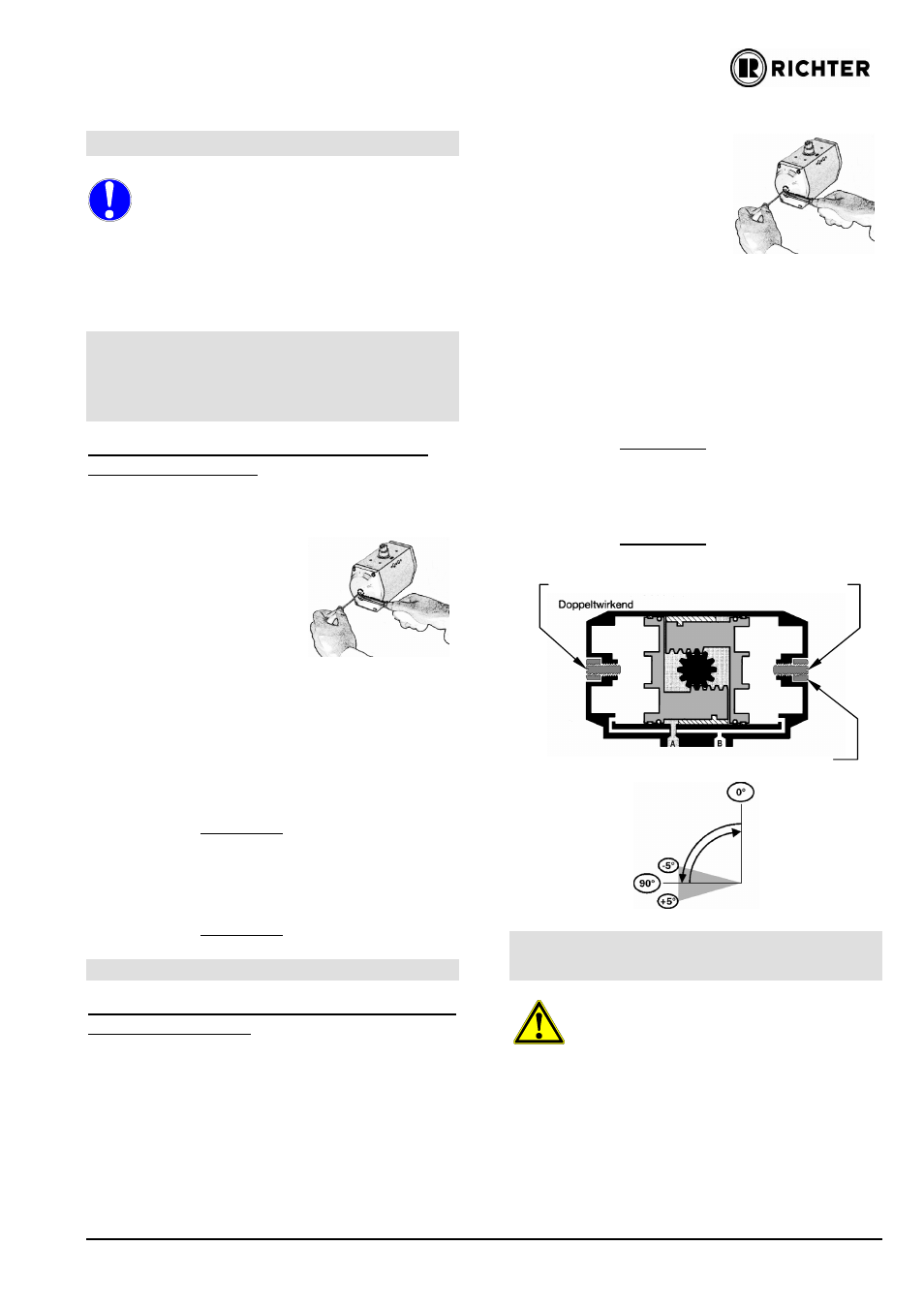
4.4.1 Double-acting actuators
Adjusting the outer stroke limiting screw for a
double-acting actuator
1. Move the piston to the switching position via ap-
plication of pressure at canal A.
2. Loosen the locking nuts
D1 and D2 at the end po-
sition adjustment screws.
3. Remove air pressure from
the actuator.
4. Turn the adjustment screw
D2 anti-clockwise ca. 5 times
5. Turn the adjustment screw D1 in one or the other
direction to reach the desired setting point for the
end position of the valve.
6. Apply air to canal A and check the adjusted posi-
tion. If required, repeat steps 3 and 5.
7. Tighten the locking nut on adjusting screw D1 with
the defined torque.
Torques see Section 1.2.
8. Turn the adjustment screw D2 clockwise against
the piston.
9. Tighten the locking nut on adjusting screw D2 with
the defined torque.
Torques see Section 1.2.
4.4.2 Single-acting actuators
Adjusting the outer stroke limiting screw for a
single-acting actuator
1. Move the piston to the switching position via ap-
plication of pressure at canal A.
2. Loosen the locking nuts
D1 and D2 at the end posi-
tion adjustment screws.
3. Remove air pressure from
the actuator.
4. Turn the adjustment screw
D2 anti-clockwise ca. 5
times
5. Turn the adjustment screw D1 in one or the other
direction to reach the desired setting point for the
end position of the valve.
6. Apply air to canal A and check the adjusted end
position. If necessary repeate proceeding (Point 3
and 5).
7. Tighten the locking nut on adjusting screw D1 with
the defined torque.
Torques
see Section 1.2.
8. Turn the adjustment screw D2 clockwise against
the piston.
9. Tighten the locking nut on adjusting screw D2 with
the defined torque.
Torques
see Section 1.2
4.5 Removal and installation of
components
Warning - Danger of injury!
Never drive the piston out of the casing with com-
pressed air.
Before working on the actuator, isolate it from the
compressed air supply.
For single-acting actuators, remove the returning
springs.
The circlip must not be over-stretched when disman-
tling.
Parts and dimensions: see drawing 9590-00-0001.
Adjusting screw D2
Locking nut
Adjusting screw D1
Canal A Canal B
Double-acting