Revel F208 User Manual
Page 7
7
Revel Performa3 F208/F206 Floorstanding Loudspeaker
Owner’s Manual
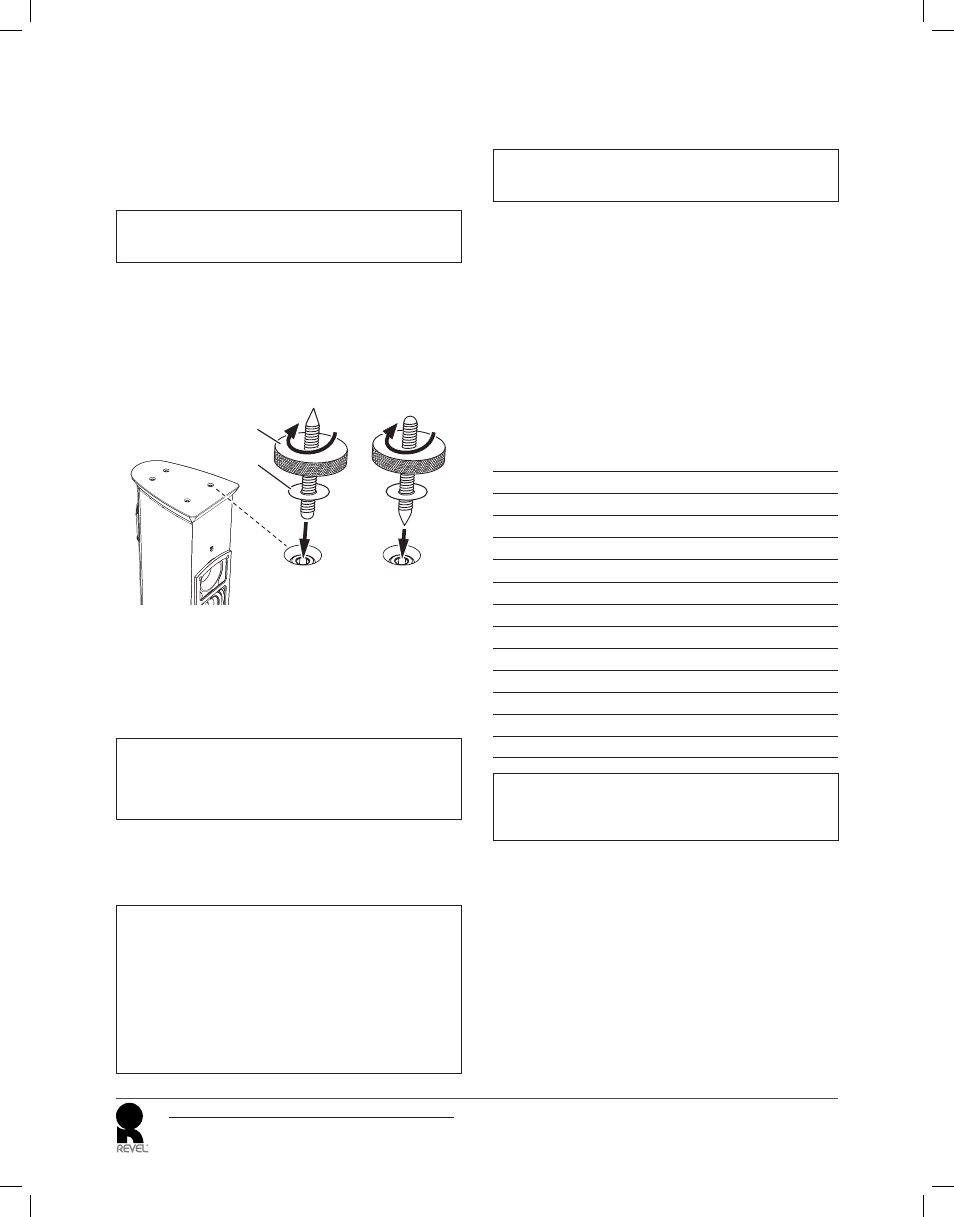
adJUStaBLe SPiKeS
Four adjustable spikes are included for each F208 and F206 loudspeaker.
You can install these spikes in the bottoms of the loudspeaker cabinets
to provide optimal stability, accommodating installations on tile,
hardwood, and carpeted fl oors.
NOTE: When moving the F208 and F206 with the spikes installed,
avoid dragging the loudspeaker across the fl oor.
To install and adjust the spikes:
1. Place the loudspeaker on its side on a soft towel or carpeted fl oor.
2. Screw the spikes into the fi ttings on the bottom of the loudspeaker.
The spikes can be installed with either the pointed end or round
end protruding from the cabinet.
Pointed
End Out
or
Rounded
End Out
Clamping Ring
(included)
Washer
(included)
• If the loudspeakers are to be placed on a carpeted fl oor, install the
spikes with the pointed ends protruding from the cabinet.
• If the loudspeakers are to be placed on a wood, linoleum or tile fl oor,
install the spikes with the round ends protruding from the cabinet.
After determining the fi nal locations for the speakers you can place
coins under the spikes to protect the fl oor surface from damage.
NOTE: If you wish you can install the spikes with the pointed ends
protruding from the cabinet for placement on wood, linoleum or
tile fl oors. In this case you must place coins or similar items under
the spikes to avoid damaging the fl oor surface.
3. Rotate the locking ring clockwise to fi rmly secure the spike to the
cabinet. Make sure to thread the locking rings of all four spikes to
achieve a level balance when the loudspeaker is placed rightside-
up on the fl oor.
CAUTION: Floor-standing loudspeakers such as the F208
and F206 have a high center of gravity, which may cause
them to fall if tipped or improperly positioned. To avoid this,
anchor the loudspeaker to the fl oor and/or wall using the
same procedures and hardware used to anchor bookcases,
wall units, and other furniture. HARMAN International
Industries, Inc. assumes no responsibility for proper
selection and installation of hardware or for any personal
injuries or product damages resulting from improper
installation or a fallen loudspeaker.
maKinG COnneCtiOnS
CAUTION: Never make or break connections unless all
system components are powered off.
OBSerVe PrOPer POLarity
Connect the amplifi er’s positive (+) terminal to the positive (+) terminal
on the corresponding speaker; connect the amplifi er’s negative (–)
terminal to the negative (–) terminal on the corresponding speaker. Do
not reverse polarities (that is, do not connect + to –, or – to +) when
making connections. Doing so will cause poor stereo imaging and
diminished bass response.
SPeaKer CaBLe
Use high-quality loudspeaker cable with a maximum total loop
resistance of 0.07 ohms or less for each wire run. Refer to the table
below to determine the appropriate wire gauge for your installation.
minimUm Wire GaUGe
Maximum Wire
Length (Feet)
Maximum Wire
Length (Meters)
Minimum Wire
Gauge (AWG)
< 87
< 27
6
< 69
< 21
7
< 58
< 18
8
< 43
< 13
9
< 34
< 10
10
< 27
< 8
11
< 22
< 7
12
< 17
< 5
13
< 14
< 4
14
< 11
< 3.5
15
< 9
< 3
16
< 7
< 2
17
< 5
< 1.5
18
NOTE: High loop resistances that exceed 0.07 ohms (for each
wire run) will cause the loudspeaker’s fi lter network to be mis-
terminated, resulting in considerable degradation of sound quality.