Anschlüsse, Bedienung, Designation – Reloop RMX-30 BPM BLACKFIRE EDITION User Manual
Page 5: Connections, Operation, Désignation, Connexions, Utilisation
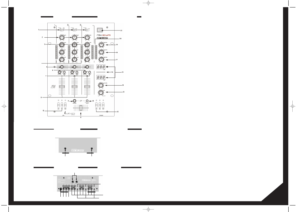
Bedienoberfläche
Vorderseite
Rückseite
5
4
Bezeichnungen:
1.
Signal-Eingangswahlschalter für Kanal 1 bis 3
2.
Gain-Regler für Kanal 1 bis 3
3.
3-fach Equalizer für Kanal 1 bis 3
4.
Aussteuerungs-LEDs für Kanal 1 bis 3
5.
Cue-Schalter für Kanal 1 bis 3
6.
Linefader Reverse Schalter für Kanal 1 bis 3
7.
Linefader Curve Regler für Kanal 1 bis 3
8.
Linefader für Kanal 1 bis 3
9.
Crossfader Reverse Schalter
10. Crossfader Curve Regler
11.
Crossfader
12. Kill Switch Einheiten für beide Crossfader-Kanäle
13. Cue-Master-Regler
14. Lautstärkeregler für Kopfhörer
15. BPM-Displays
16. Beat Offset-LED
17. Lautstärkeregler für Masterausgang 2
18. Balance-Regler für Masterausgang
19. Lautstärkeregler für Masterausgang
20. Aussteuerungs-LED für Mastersignal
21. EIN/AUS Schalter
22. Eingangsbuchse für Mikrofon (6,3 mm Klinke)
23. Ausgangsbuchse für Kopfhörer (6,3 mm Klinke)
24. Eingang für externes Netzteil
25. Master 1 Ausgangsbuchsen (Cinch)
26. Master 2 Ausgangsbuchsen (Cinch)
27. REC Ausgangsbuchsen (Cinch)
28. Eingangsbuchsen für Kanal 1 bis 3 (Cinch)
29. Phono/Line Umschalter für Kanal 1 bis 3
30. GND Erdungsschrauben
31. Master 1 Ausgangsbuchsen (6,3 mm Klinke)
Anschlüsse
1. Verbinden Sie Ihre Linequellen (CD-Player, MiniDisc, DAT, etc.)
und Ihre Plattenspieler mit den Eingangsbuchsen für Kanal 1
bis 3 -28-. Wenn Sie an die "Phono"-Buchsen Plattenspieler
anschließen möchten, so stellen Sie den/die Phono/Line
Umschalter -29- in die Position "Phono"; möchten Sie an diese
Buchsen Linequellen anschließen, so stellen sie den/die
Phono/Line Umschalter in die Position "Line".
ACHTUNG!
Stellen Sie sicher, dass während der Betätigung der
Phono/Line Umschalter das Gerät ausgeschaltet ist.
2. Verbinden Sie die Erdungskabel Ihrer Plattenspieler mit der
jeweiligen GND Erdungsschraube -30-.
3. Verbinden Sie Ihr Mikrofon mit der Eingangsbuchse Mic -22-.
4. Verbinden Sie Ihren Kopfhörer mit der Ausgangsbuchse für
Kopfhörer -23-.
5. Verbinden Sie Ihre Hauptanlage je nach Bedarf mit den Master
1 Ausgangsbuchsen -25- (Cinch) oder mit den Master 1
Ausgangsbuchsen -31- (6,3 mm Klinke).
6. Verbinden Sie Ihre Monitor-Anlage mit den Master 2
Ausgangsbuchsen -26-.
7. Verbinden Sie ein Aufnahmemedium Ihrer Wahl mit den REC
Ausgangsbuchsen -27-.
8. Schließen Sie das externe Netzteil an den entsprechenden
Eingang -24- an.
Bedienung
1. Strom einschalten
Nachdem alle Anschlüsse vorgenommen wurden, das Gerät mit
dem EIN/AUS Schalter -21- einschalten.
2. Signal-Eingangswahl
Mit den Signal-Eingangswahlschaltern -1- können Sie für Kanal
1 bis 3 zwischen Line-, Phono und Mikrophonquelle wählen.
Beachten Sie dazu die Beschriftung der einzelnen Signal-
Eingangswahlschalter wie auch die Stellung der Phono/Line
Umschalter -29-.
3. Gain
Mit den Gain Reglern -2- wird die Eingangslautstärke für Kanal
1 bis 3 eingestellt.
Designation:
1.
Signal input selector for channels 1 to 3
2.
Gain control for channels 1 to 3
3.
3-fold equalizer for channels 1 to 3
4.
Modulation LEDs for channels 1 to 3
5.
Cue switch for channels 1 to 3
6.
Linefader reverse switches for channels 1 to 3
7.
Linefader curve controls for channels 1 to 3
8.
Linefaders for channels 1 to 3
9.
Crossfader reverse switch
10. Crossfader curve controls
11.
Crossfader
12. Kill switch units for both crossfader channels
13. Cue-Master control
14. Volume control for headphones output
15. BPM displays
16. Beat Offset LED
17. Volume control master output 2
18. Balance control master output
19. Volume control master output
20. Modulation LED for master signal
21. ON/OFF switch
22. Input jack for mic (XLR/ 6.3 mm jack plug)
23. Output jack for headphones (6.3 mm jack plug)
24. Input jack for external power pack
25. Master 1 output jacks (cinch)
26. Master 2 output jacks (cinch)
27. REC output jacks (cinch)
28. Input jacks for channels 1 to 3 (cinch)
29. Phono/line change-over for channels 1 to 3
30. GND grounding screws
31. Master 1 output jacks (6,3 mm jack plug)
Connections
1. Connect your line sources (CD player, MiniDisc, DAT, etc.) and
your turntables with the input jacks for channels 1 to 3 -28-. If
you wish to connect (a) turntable(s) to the "Phono" jacks
switch the phono/line change-over switches to the "Phono"-
position. If you intend to hook up (a) line source(s) to these
jacks simply switch the phono/line change-over switch -29- to
the "Line"-position.
ATTENTION!
When operating the phono/line change-over switches
always make sure that the unit is switched of.
2. Connect the ground cable of your turntables with the
respective GND ground screw -30-.
3. Connect your microphone with the Mic input jack -22-.
4. Connect your headphones with the output jack for headphones
-23-.
5. Connect your main unit according to your requirements with
the Master 1 output jacks -25- (cinch) or with the Master 1
output jacks -31- (6,3 mm jack plug).
6. Connect your monitor unit with the Master 2 output jacks -26-.
7. Connect the recording equipment of your choice with the REC
output jacks -27-.
8. Hook up the external power pack with the respective input -24-.
Operation
1. Power on
After making all connections turn on the power with the
ON/OFF switch -21-.
2. Signal selector
The signal input selector -1- allows you to choose between line,
phono and mic source for channels 1 to 3. Please observe the
designation of the individual signal input selectors as well as
the positions of the Phono/line change-over switches -29-.
3. Gain
The gain control -2- sets the input volume for channels 1 to 3.
Désignation:
1.
Sélecteur de signal d'entrée pour les canaux 1 à 3
2.
Régleur de gain pour les canaux 1 à 3
3.
Égaliseur trois voies pour les canaux 1 à 3
4.
DEL de saturation pour les canaux 1 à 3
5.
Touche CUE pour les canaux 1 à 3
6.
Touche d'inversion du curseur linéaire pour les canaux 1 à 3
7.
Régleur de courbe du curseur linéaire pour les canaux 1 à 3
8.
Curseur linéaire pour les canaux 1 à 3
9.
Crossfader Reverse
10. Régleur de courbe du Crossfader
11.
Crossfader
12. Unités Kill Switch pour les deux canaux Crossfader
13. Régleur Cue-Master
14. Volume du casque
15. Affichage BPM
16. DEL Beat Offset
17. Volume pour la sortie Master 2
18. Balance pour la sortie Master
19. Volume pour la sortie Master
20. DEL de saturation pour le signal Master
21. Interrupteur MARCHE/ARRÊT
22. Fiche d'entrée microphone (6,3 mm jack)
23. Fiche de sortie casque (6,3 mm jack)
24. Entrée du bloc d'alimentation externe
25. Fiches de sortie Master 1 (coaxiales)
26. Fiches de sortie Master 2 (coaxiales)
27. Fiches de sortie REC (coaxiales)
28. Fiches d'entrée pour les canaux 1 à 3 (coaxiales)
29. Commutateurs Phono/Line pour les canaux 1 à 3
30. Vis de terrage GND
31. Fiches de sortie Master 1 (6,3 mm jack)
Connexions
1. Connectez vos sources Line (lecteur de CD, MiniDisc, DAT, etc.)
et votre platine vinyle avec les fiches d'entrée pour les canaux
1 à 3 -28-. Si vous désirez connecter une platine vinyle aux
connecteurs "Phono", il faut régler les commutateurs
Phono/Line -29- sur la position "Phono"; si vous désirez
connecter des source Line, réglez les commutateurs
Phono/Line sur la position "Line".
ATTENTION !
Avant de régler les commutateurs Phono/Line, contrôler
si l'appareil est éteint !
2. Branchez le câble de mise à terre de votre platine vinyle sur la
vis de terrage GND respective -30-.
3. Connectez votre microphone sur la fiche d'entrée Mic -22-.
4. Connectez votre casque sur la fiche de sortie casque -23-.
5. Connectez votre chaîne selon vos besoins sur les fiches de
sortie Master 1 -25- (coaxiales) ou sur les fiches de sortie
Master 1 -31- (6,3 mm jack).
6. Connectez votre Monitor sur les fiches de sortie Master 2 -26-.
7. Connectez votre appareil d'enregistrement de votre choix sur
les fiches de sortie REC -27-.
8. Raccordez le bloc d'alimentation externe à son entrée -24-.
Utilisation
1. Mise en marche
Après avoir effectué toutes les connexions, appuyez sur
l'interrupteur MARCHE/ARRÊT -21- pour allumer la console.
2. Sélection du signal d'entrée
Le sélecteur de signal d'entrée -1- vous permet de sélectionner la
source Line, Phono ou micro pour les canaux 1 à 3. Observez pour
cela l'indication des différents sélecteurs de signal d'entrée, ainsi
que la position des commutateurs Phono/Line -29-.
3. Gain
Le régleur de gain -2- permet de régler le volume d'entrée pour
les canaux 1 à 3.
4
31
24 25
22
26 27
28
30
23
29
Controls
Front Panel
Rear Panel
Panneau de commande
Face avant
Face arrière
instrManual_RMX-30BPM_blackfire.qxd 03.04.2007 12:51 Uhr Seite 4