Front panel, Customizing the illusion ii, Remote control back panel – Krell Illusion II Preamplifier User Manual
Page 2: Configurable functions, Navigation conventions
1
5
9
7
8
6
3
10
2
4
2 Krell Illusion II
Krell Illusion II 3
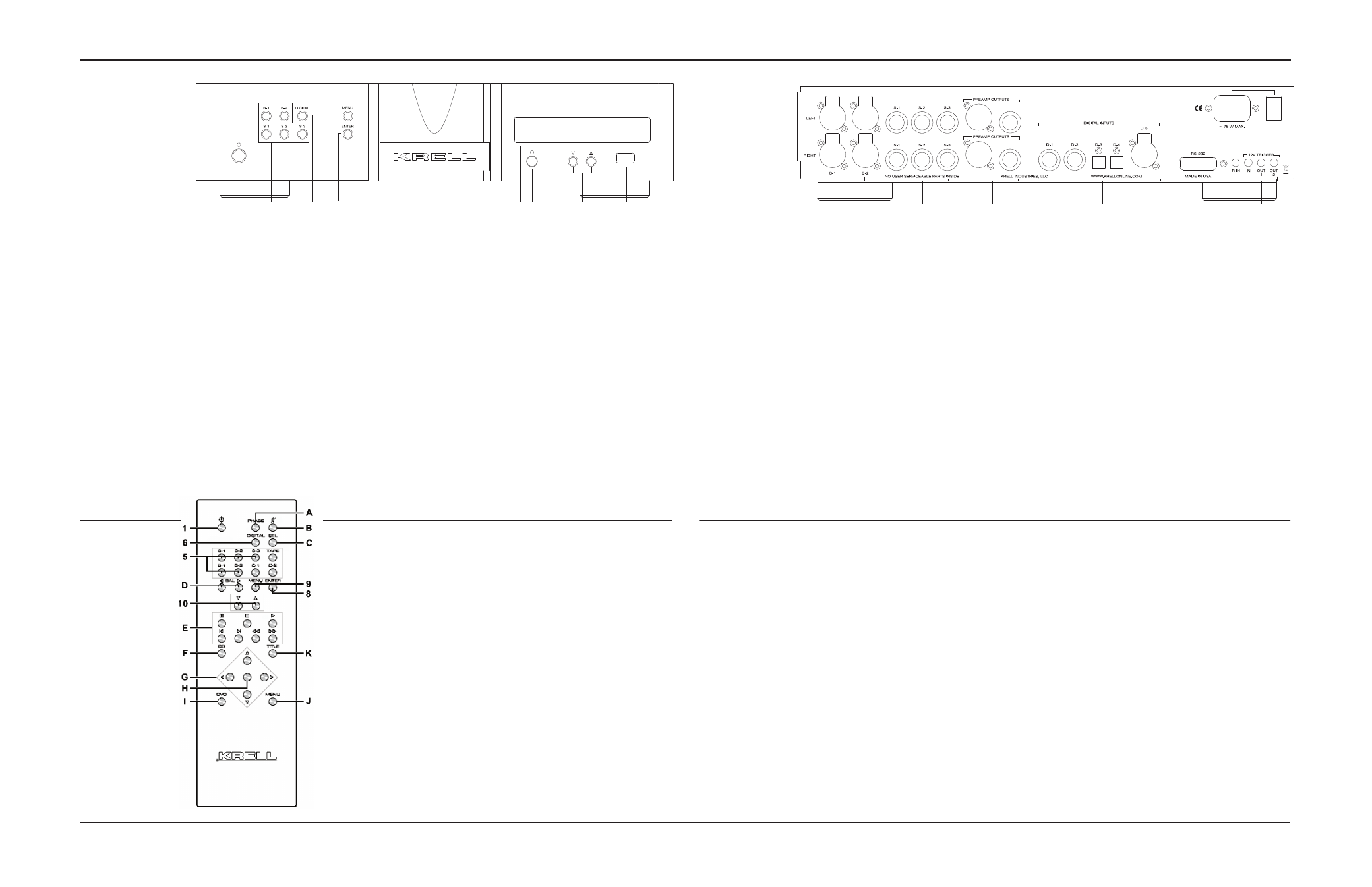
Figure 1 The Illusion II Front Panel
Figure 2 The
Illusion II
Remote Control
Figure 3 The Illusion II Back Panel
11
12
18
13
14
16
17
15
This product is manufactured in the United States of America. Krell
®
is a registered trademark of Krell Industries, LLC., and is restricted for
use by Krell Industries, LLC. its subsidiaries, and authorized agents. Krell Current Mode™ and CAST™ are trademarks of Krell Industries,
LLC. All other trademarks and trade names are registered to their respective companies.
© 2014 by Krell Industries, LLC., All rights reserved.
Front Panel
11 Balanced inputs: B-1
and B-2
These XLR balanced
analog source input
connectors are wired
as follows:
Pin 1 Ground
Pin 2 Non-inverting
Pin 3 Inverting
12 Single-ended inputs:
S-1, S-2, and S-3
There are 3 single-
ended analog source
inputs with RCA
connector pairs.
13 Main outputs
The Illusion II is
equipped with one
balanced XLR output
pair and one single-
ended RCA output pair.
Customizing
the
Illusion II
1 Power
Use this to switch the
preamplifier between
stand-by and operational
modes.
2 Display
This provides channel
status messages,
in-cluding input selection,
volume level, balance
offset, and menu
selections.
3 Infrared sensor
This receives commands
from the remote control.
Make sure this is not
obstructed.
4 Stand-by/Power
indicator
This power indicator
illuminates red (stand-
by) when the Illusion II is
plugged into a standard
AC wall receptacle
and rear power switch
is on. The power
indicator illuminates
blue (operational mode)
when the power button
(1) is pressed while the
Illusion II is in stand-by
mode.
5 Analog Input selectors
Use these to select
the corresponding
rear panel input that is
connected to a single-
ended (S-1, S-2, S-3),
or balanced (B-1, B-2)
analog source. The
display (2) shows the
selected input and
volume level. Pressing
the input button on the
active source will mute
all outputs. A second
press will unmute the
outputs.
6 Digital Input selector
Use this to select the
D/A converter module.
Pressing and holding the
digital button will cycle
through the additional
digital inputs.
7 Headphone Jack
1/4" stereo headphone
jack. The main outputs
are muted when
headphones are being
used.
8 Enter button
Use this to configure the
menu functions of the
Illusion II. See menu (9).
9 Menu button
Use this to access the
menu functions of the
Illusion II.
10 Level control buttons
Use these buttons to
increase or decrease
system volume level.
The level control buttons
or keys also select menu
options that customize
the Illusion II.
14 RS-232 port
This port receives
messages from a
computer-based control
system, providing
integrated control of all
preamplifier functions.
15 RC-5 in
This remote connector
is used with third-party
remote control systems
that provide RC-5
(IR) data via a wired
connection. A stereo tip,
ring, sleeve 1/8” mini
connector is used in the
following configuration:
Tip = RC-5 data
Ring = +5 V
Sleeve = GND.
16 12 VDC in/out
(12 V trigger)
There are 2 outputs
and one input that send
Configurable
Functions
AC Mains
Balance (channel)
Balance (input trim)
Display, Info
Input Level Trim
Input Name, Input Phase
Input Trigger, Mute,
Output Trigger, Recall,
Save, Theater.
The menu button or key
(9) allows you to configure
functions. Enter the menu to
view the list of configurable
functions.
Select a function to view
a submenu of the list of
options that configure the
function. You can configure
some options as well, if a
second submenu appears
when you select an option.
Navigation
Conventions
Navigating the preamplifier
menu is straightforward and
consistent throughout, using
4 functions and the menu
option BACK.
9 Menu Button or Key
To enter the menu,
press the menu button
or key. Once you are in
the menu, you can press
the menu button or key
to exit the menu.
10 Level Control Buttons
or Up and Down Keys
Use the level control
buttons or the up and
down keys on the
re-mote control to scroll
forward and backward
through the menu
hierarchy. Each menu
list is a continuous loop.
8 Enter Button or Key
Press this button or key
to select a function or a
configuration option, and
confirm a selection
3 Front Panel Display
The display shows the
active function and
configurable options.
BACK
Select
BACK
to scroll
backwards through
the menu hierarchy, or
to exit a menu option
without confirming that
option.
and receive 12 VDC
power on/off (trigger)
signals to and from
other Krell components,
and other devices
that incorporate a 12
V trigger. This allows
other components to be
turned on/off, or to/from
stand-by, through the
remote control.
17 IEC power cord
receptacle and power
switch
This is for use with the
provided AC power
cord. Plug the other end
into an AC Mains supply
capable of supplying the
correct AC voltage and
current for the power
supply. This connector
and power cord must
remain unobstructed for
easy removal in case of
an emergency.
18 Digital inputs: D-1,
D-2, D-3, D-4, and D-5
There are 2 coaxial
inputs using RCA
connectors, 2 optical
connectors using Toslink
connectors, and 1 AES/
EBU using an XLR
connector.
Keys labeled 1 to 10
have the same function
(and callout number) as
the front panel controls.
Keys labeled A through
K are unique to the
re-mote control, and are
described below:
A Phase key
Inverts the polarity
of the audio signal. A
lowercase i is displayed
when the polarity is
inverted.
B Mute key
Use this mute all
outputs. A second press
of the mute key will
unmute the outputs.
C Sel(ect) key
Cycles through the
digital inputs.
D Bal(ance) keys
Use to balance left and
right output levels.
E Transport keys
These keys are
functional with all Krell
CD and DVD players.
F CD key
Press this to make the
transport keys operate
Krell CD players.
G Direction keys
Use these keys to
navigate CD and DVD
menus.
H Select Key
Use this to make
selections from CD and
DVD menus.
I DVD key
Press this to make the
transport keys operate
DVD players.
J Menu key
Use this to enter CD or
DVD player menus.
K Title key
Use this with CD or
DVD player menus.
Note
The remote is shipped
with two AAA batteries
that have to be instal-
led. Use the supplied
Torx wrench to remove
the battery panel, then
install the batteries.
Remote
Control
Back Panel