Front panel, Power supply remote control, Back panel – Krell Illusion Preamplifier User Manual
Page 2: Figure 4 the illusion power supply
1
2
5
4
9
8
7
6
3
2 Krell Illusion
Krell Illusion 3
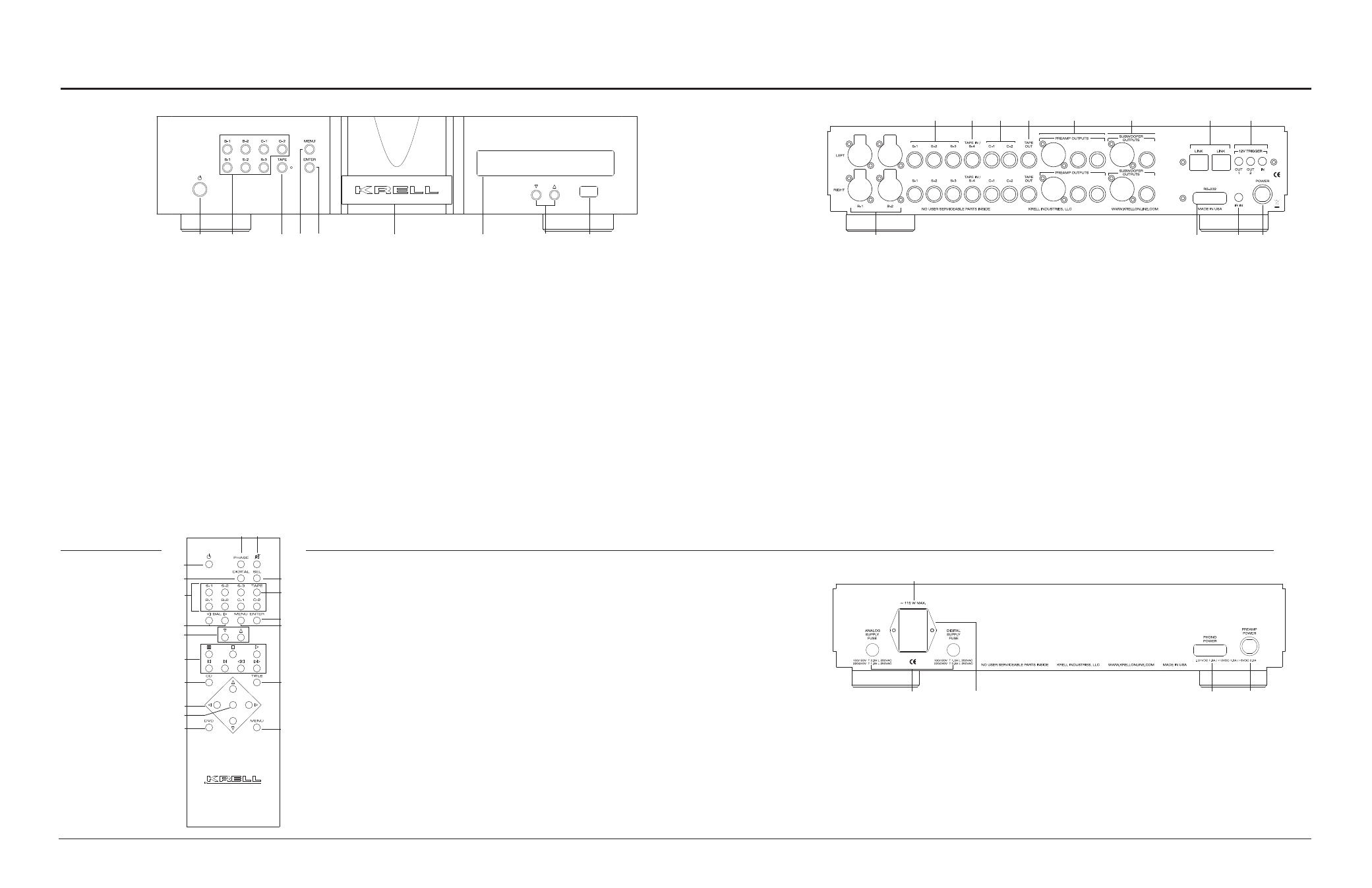
Figure 1 The Illusion Front Panel
Figure 2 The
Remote Control
Figure 3 The Illusion Back Panel
15
16
18
23
25
22
24
17
19
20
21
26
This product is manufactured in the United States of America. Krell® is a registered trademark of Krell Industries, LLC., and is restricted for
use by Krell Industries, LLC. its subsidiaries, and authorized agents. Krell Current Mode™ and CAST are trademarks of Krell Industries,
LLC. All other trademarks and trade names are registered to their respective companies.
© 2014 by Krell Industries, LLC., All rights reserved
Front Panel
27
29
30
28
31
Power Supply
Remote
Control
Figure 4 The Illusion Power Supply
1
D
F
2
5
A
C
B
8
L
G
3
E
4
J
K
H
I
1 Power
Use this to switch the
preamplifier between stand-by
and operational modes.
2 Input selectors
Use these to select the
corresponding rear panel input
that is connected to a single-
ended (S-1, S-2, S-3), balanced
(B-1, B-2), or CAST (C-1, C-2)
analog source. The display (7)
shows the selected input and
volume level.
3 Tape input selector
Use this to select the tape
input that is connected to an
analog tape source. The blue
LED illuminates when the tape
input is selected. The display
(7) shows: TAPE and the main
volume level.
4 Menu button
Use this to access the menu
functions of the Illusion.
5 Enter button
Use this to configure the menu
functions of the Illusion. See
Menu (4).
6 Stand-by/Power Indicator
The power indicator illuminates
red (stand-by) when the Illusion
is plugged into a standard AC
wall receptacle. The power
indicator illuminate blue
(operational mode) when the
power button (1) is pressed
while the Illusion is in stand-by
mode.
7 Display
This provides channel status
messages, including input
selection, volume level, balance
offset, and menu selections.
8 Level control buttons
Use these buttons to increase
or decrease system volume
level. The level control buttons
or keys also select menu
options that customize the
Illusion.
9 Infrared sensor
This receives commands from
the remote control. Make sure
this is not obstructed.
Back Panel
15 Balanced inputs: B-1 and
B-2
These XLR balanced
analog source input
connectors are wired
as follows:
Pin 1 Ground
Pin 2 Non-inverting
Pin 3 Inverting
16 Single-ended inputs:
S-1, S-2, and S-3
There are 3 single-ended
analog source inputs with
RCA connector pairs.
17 Tape input
This single-ended input
pair is for use with a tape
source.
18 C-1 and C-2 inputs
The two CAST inputs have
4-pin bayonet connectors,
for use with Krell CAST-
equipped input devices.
19 Tape output
This single-ended output
pair is used for recording
the selected input source.
20 Main outputs
The Illusion is equipped
with one balanced XLR
output pair, one single-
ended RCA output pair, and
two CAST output pairs with
4-pin bayonet connectors
(for use with Krell CAST-
equipped amplifiers).
21 Subwoo fer
The Illusion is equipped
with one balanced XLR
and one single-ended
RCA subwoofer output
pair. Note: These outputs
are only active when the
Illusion is equipped with the
optional crossover board.
22 CAN link
These RJ-45 link
connectors are connected
in parallel. They are used
to operate preamplifier
channels in linked mode.
23 RS-232 port
This port receives
messages from a
computer-based control
system, providing
integrated control of all
preamplifier functions.
24 RC-5 in
This remote connector
is used with third-party
remote control systems
that provide RC-5 (IR) data
via a wired connection. A
stereo tip, ring, sleeve 1/8”
mini connector is used in
the following configuration:
Tip = RC-5 data
Ring = +5 V
Sleeve = GND.
25 DC power connector
Use the supplied 12-pin
cable to connect this to
the corresponding DC
power connector on the
power supply. Make sure
the AC power cord is
unplugged before making
any connections to the
preamplifier.
26 12 VDC in/out
(12 V trigger)
There are 2 outputs and
one input that send and
receive 12 VDC power
on/off (trigger) signals
to and from other Krell
components, and other
devices that incorporate a
12 V trigger. This allows
other components to be
turned on/off, or to/from
stand-by, through the
remote control.
Keys labeled 1 to 9
have the same function
(and callout number) as
the front panel controls.
Keys labeled A through
L are unique to the
re-mote control
A Phase button
Use this to invert the
absolute polarity of the
main output.
B Mute button
Use this to mute the
preamplifier output. To
unmute, press the mute
button again.
C Digital button
Unused
D Sel(ect) button
Unused
E Bal(ance) keys
Use to balance left and
right output levels.
F Transport k eys
These keys are
functional with all Krell
CD and DVD players.
G Menu key
Use this to enter CD or
DVD player menus.
H Direction keys
Use these keys to
navigate CD and DVD
menus.
I Select key
Use this to make
selections from CD and
DVD menus.
J CD key
Press this to make the
transport keys operate
Krell CD players.
K DVD key
Press this to make the
transport keys operate
DVD players.
L Title key
Use this with CD or
DVD player menus.
Note
Use the supplied Torx
wrench to remove the
battery panel, then
install the included AAA
batteries.
27 Fuses
Always unplug the power
cord before inspecting
these fuses. Always
replace the fuses with the
exact style and rating.
28 IEC power cord
receptacle
This is for use with the
provided AC power cord.
Plug the other end into an
AC Mains supply capable
of supplying the correct AC
voltage and current for the
power supply.
29 Phono power port
This is for connecting the
preamplifier to a Krell KPE
phono stage. See the KPE
owner’s reference for more
details.
30 DC power connector
Use the supplied 12-pin
cable to connect this to
the corresponding DC
power connector on the
preamplifier. Make sure
the AC power cord is
unplugged before making
any connections to the
preamplifier.
31 Main Power Switch
Press the “1” to put the
preamp in the standby
mode. Press the “0” to
power the preamplifier
off completely. The
switch should remain
unobstructed for ease of
operation and in case of an
emergency.