Front panel back panel, Remote control, Figure 4 connection diagram – Krell S-550i User Manual
Page 2
2 Krell S-550i
Krell S-550i 3
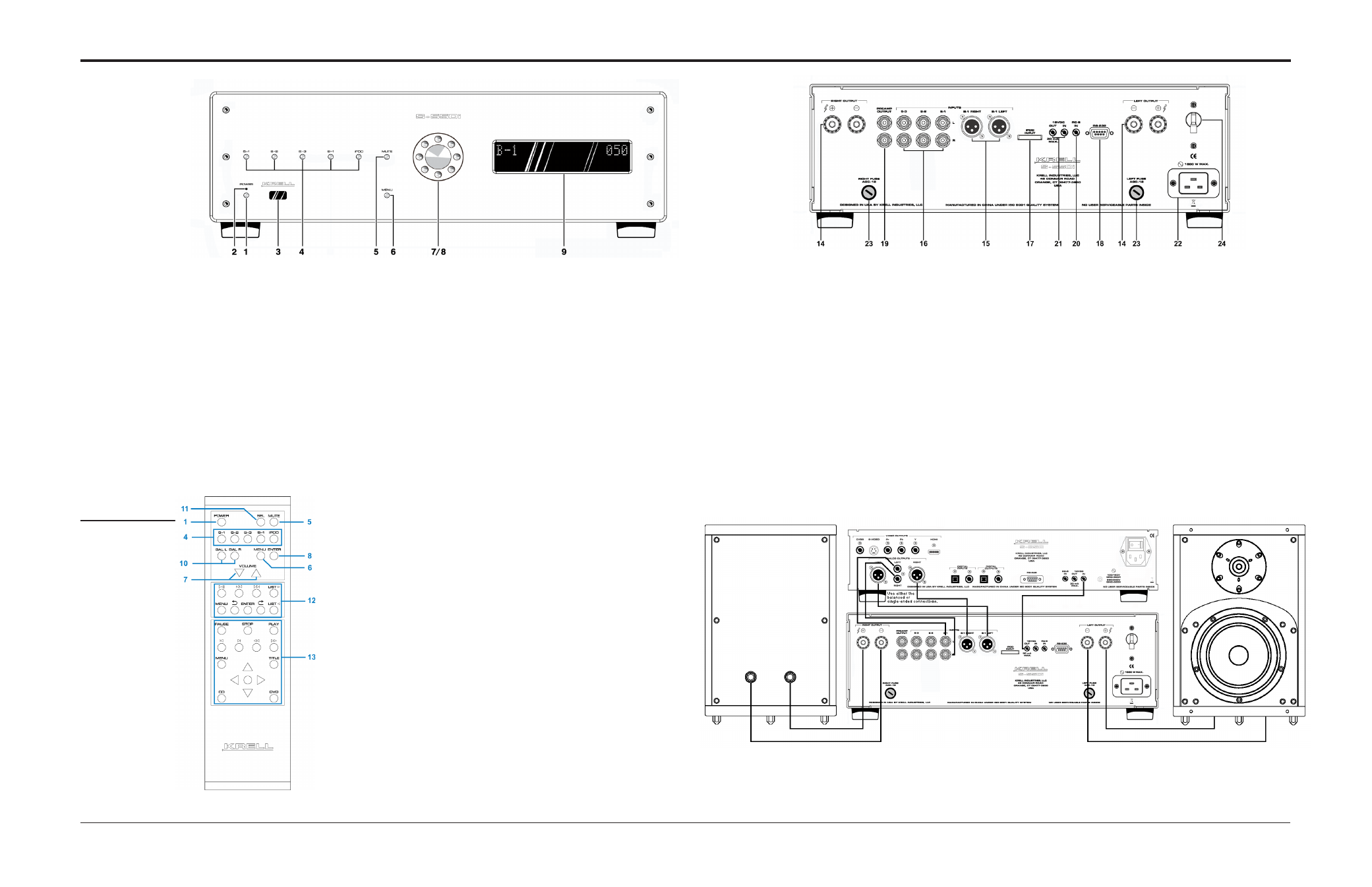
Figure 1 The S-550i Front Panel
Figure 2 The
Remote Control
Figure 3 The S-550i Back Panel
This product is manufactured in the United States of America. Krell® is a registered trademark of Krell Industries, LLC., and is restricted for
use by Krell Industries, LLC. its subsidiaries, and authorized agents. Krell Current Mode™ is a trademark of Krell Industries, LLC. All other
trademarks and trade names are registered to their respective companies.
© 2011 by Krell Industries, LLC., All rights reserved
Front Panel
Back Panel
1 Power Button
Use this button to
switch the S-550i
between stand-by and
operational modes.
2 Stand-by LED
The stand-by LED
illuminates red when
the S-550i is plugged
into a standard AC
wall receptacle and
the rear panel power
breaker switch is in the
up position, indicating
that the amplifier is in
the stand-by mode and
ready to be switched to
the operational mode.
The LED illuminates
blue when the S-550i is
in operational mode.
3 Infrared sensor
This receives com-
mands from the remote
control. Make sure this
is not obstructed.
4 S-1, S-2, S-3, B-1 and
iPod Buttons
Use these buttons to
select a balanced ana-
log source component
(B-1) via an XLR con-
nector, or a single-
ended analog source
component (S-1,
S-2, or S-3) via single-
ended RCA connec-
tors, or an iPod via a
special 30-pin iPod
dock.
5 Mute button
Use this to mute the S-
550i output. To unmute,
press the mute button
again.
6 Menu button
Use this to access the
menu functions of the
S-550i.
7 Level Control knob /
Level Keys
The level knob on the
front panel or the level
keys on the remote
control adjust the
amplifier output level.
The output level is
indicated numerically
on the front panel dis-
play, with a range from
0-151.
8 Level Control knob /
Enter Key
Press the level knob
or use the enter key
to configure the menu
functions of the S-550i.
9 Front Panel Display
The front panel dis-
play shows the input
selected, volume and
balance levels, and
Theater Throughput
status.
14 Loudspeaker Outputs
The S-550i is equipped
with standard binding
posts for each amplifier
channel.
15 Balanced Analog Inputs
The S-550i is equipped
with one pair of balanced
(B-1) inputs via XLR con-
nectors.
16 Single-Ended Analog
Inputs
The S-550i is equipped
with three pairs of single-
ended (S-1, S-2, or S-3)
inputs via RCA connec-
tors.
17 iPod Input
The S-550i is equipped
with a balanced stereo
iPod input via a locking
30-pin connector. The
required iPod dock is
supplied.
18 RS-232
The RS-232 port receives
messages from a com-
puter-based control sys-
tem, providing integrated
controls of all integrated
functions. The RS-232
input uses a 9-pin D-sub-
miniature connector.
19 Preamp Outputs
The S-550i is equipped
with a pair of single-
ended preamplifier
oututs.
20 RC-5 In
The S-550i is equipped
with an RC-5 input that
makes custom instal-
lation easy and secure
by accepting baseband
RC-5 input commands
from a remote IR detec-
tor or hardwired remote
controllers.
21 12 VDC In/Out (12 V
trigger)
The 12 V Trigger input
allows you to place the
S-550i into the stand-
by or operational mode
from other components.
The 12 V trigger output
allows the S-550i to
turn other components
on or off.
22 IEC Connector
The connector is for use
with the provided IEC stan-
dard 20 amp power cord.
This connector and power
cord must remain unob-
structed for easy removal
in case of emergency.
23 Speaker Fuses
The speaker fuses pro-
tect the S-550i and the
loudspeakers in case of
overload, short circuit, or
malfunction.
24 AC Power Breaker
Switch
Use this switch to change
the S-550i from off to the
stand-by mode.
Keys labeled 1 to 8
have the same function
(and callout number) as
the front panel controls.
10 BAL (Balance) Keys
Use these keys to shift
the balance to the left
or the right channel.
11 SEL (Select) Key
Used to select
advanced meter or dis-
play functions on other
current Krell products.
12 Direct iPod Functions
With an iPod con-
nected to the special
iPod dock, basic con-
trol functions are avail-
able from the remote
control.
13 CD / DVD Transport
Control
Used to control basic
CD / DVD functions
on other current Krell
products (S-350a).
Note
The remote comes with
two AAA batteries that
have to be installed.
Use the supplied Torx
wrench to remove the
battery panel, then
install the batteries.
Remote
Control
Figure 4 Connection Diagram