JK Audio Concierge 2x6 User Manual
Page 7
7
Reserved
8
Reserved
9
Reserved
10
Guest Module Programming Mode
11
Switch Core Programming Mode
12
Accessory Enable (name TBD)
Dip Switches
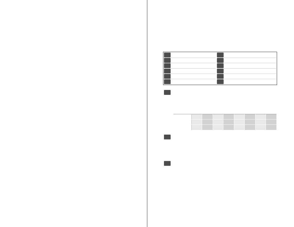
The Concierge™ 2x6 Switch Core is equipped with 12 slide style DIP switches
located underneath the removeable cover plate on the front. Configure your
Concierge by enabling or disabling features by switching between the ON and
OFF positions for each DIP switch. The following chart shows each feature and
it’s corresponding switch.
Auto-Drop
OFF (Default): Places the current call on Hold when either a Line button,
Next, or Previous button is pressed.
ON:
Will drop the current call when either a Line button, Next or Previous
button is pressed, unless the call is manually placed on Hold.
Slave
For 12-line systems:
OFF (Default):
In the ‘Off’ position, the Concierge behaves as the master
device, controlling the first 6 lines.
ON
:
When bridging two Concierge Switch Cores, use the Expansion bus
to create a 12-Line system. Flip the Slave DIP switch to the ‘On’ position
to convert Lines 1-6 to Lines 7-12 on the second Concierge Switch Core.
Ring Count
1
2
3
4
5
6
7
8
Auto-Ring 0
OFF
ON
OFF
ON
OFF
ON
OFF
ON
Auto-Ring 1
OFF
OFF
ON
ON
OFF
OFF
ON
ON
Auto-Ring 2
OFF
OFF
OFF
OFF
ON
ON
ON
ON
Auto Ring (Default = 1 Ring)
The Auto-Ring DIP switches select the Auto Answer Ring Count whenever
the Auto Answer function is enabled. The Ring Count number is controlled
by a combination of the three Auto-Ring switches.
4
1-3
5
1
Auto-Ring 0
2
Auto-Ring 1
3
Auto-Ring 2
4
Auto-Drop
5
Slave
6
Reserved
Step 1: Phone Line Wiring
Connect each phone line directly to the RJ-11 jacks on the back of the
Concierge. Auxiliary phones should be connected to the 1/A or 2/B Phone Ports
for proper system integration. Do not use external line splitters to connect an Aux
phone. Do not connect an Aux phone to the innkeeper digital hybrid.
Step 2: Hybrid Connection
Two cables join each hybrid to the Concierge Switch Core. An RJ11 Modular
phone cord connects the innkeeper Phone Line jack to the Concierge 1/A or 2/B
Hybrid Phone Port. The remote data cable connects the innkeeper remote jack to
the Concierge Hybrid Remote jack.
Step 3: Guest Module Control Surfaces
A maximum of four guest modules can be connected to each of the two
Guest Module ports, for a system maximum of eight Guest Modules. The dual
connection ports on each Guest Module allow for quick daisy-chain wiring, or
you may simply run all cables back to a terminal block to allow for point-to-point
wiring. The maximum distance from Concierge to the farthest Guest Module is a
function of the number of Guest Modules connected, as well as the the gauge of
the wire chosen. Standard 26 gauge cable can be used on runs shorter than 100
feet, but as distance and the number of units increase, you may need to consider
24 gauge CAT5 wire.
While Guest Modules use standard CAT5 cable, the communications protocol
is balanced differential RS-485 using a custom pinout. This is not an Ethernet
connection, and should not be connected to a data hub or switch.
2x12 Expansion
Two Concierge switch cores can be bridged together into a 2x12 system,
providing six additional phone lines. Begin with both Concierge Switch Cores
powered down. On the second Concierge, DIP switch 5 must be set to the ON
position, shifting line assignment to lines 7-12. Now connect the phone and data
expansion bus cables from the first unit to the second unit. Upon power-up, both
units will display a green “Bridge” LED indicating that they are now properly
communicating. Only GM1x12 control surfaces can be connected to a bridged
system. The GM1x12 control surfaces can be connected to either the 1/A or 2/B
control bus on the Master (1-6) Concierge Switch Core. All hybrid and Guest
Modules connections are made through the Master Concierge unit. Only the
Phone Line and Expansion Bus jacks are used on the Slave Concierge unit.
8
Concierge™ 2x6
Switch Core
Configuring the Concierge™ 2x6
9
Installing
Configuring the Concierge™ 2x6