0 installation and commissioning, 1 mounting & site selection – HF scientific CLX Online Residual Chlorine Monitor User Manual
Page 11
CLX (1/12)
Page 6
REV 5.1
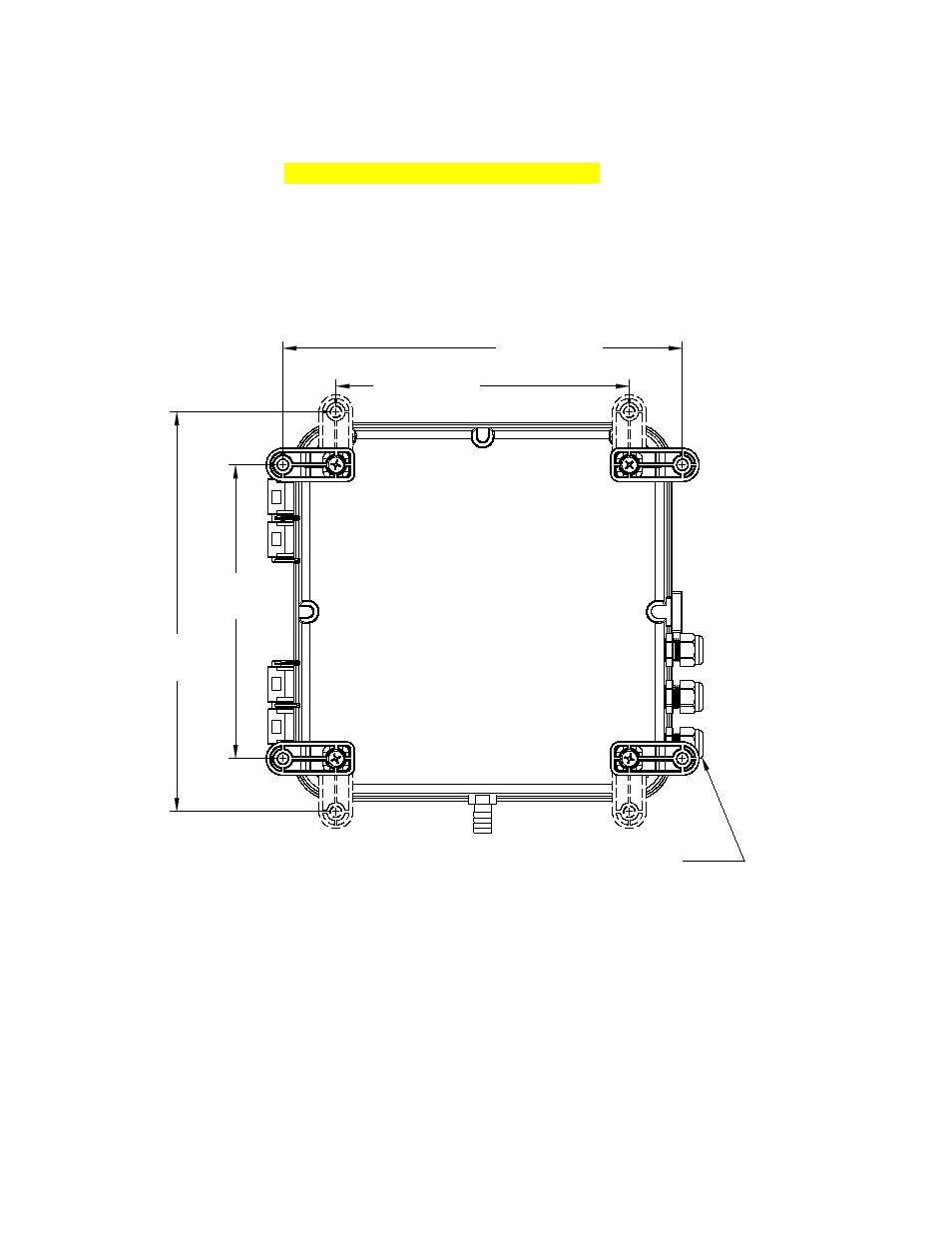
IT MAY B E NEC ESSARY TO REMOVE
TH IS B ULK H EAD NUT TO AC C ESS TH E
B OTTOM LEFT MOUNTING H OLE WITH
TH E B RAC K ET IN TH IS POSITION.
REAR VIEW
OF TH E
INSTRUMENT
2 1 9 .0 8 m m
( 8 .6 2 5 " )
2 9 8 .4 5 m m
( 1 1 .7 5 0 " )
2 1 9 .0 8 m m
( 8 .6 2 5 " )
2 9 8 .4 5 m m
( 1 1 .7 5 0 " )
4.0
Installation and Commissioning
Prior to use for the first time, one of the reagents (the indicator) will have to be mixed.
Refer to section 10.2 Replacing or Installing the Reagents.
4.1 Mounting & Site Selection
The instrument is designed for wall mounting. If wall mounting is not practical, the
instrument can be mounted on any suitable level surface Choose a location that is easily
accessible for operation and service and ensure that the front display rests at eye level.
Consideration must be made the plumbing connections. The overall mounting dimensions
of the instrument are shown in Figure 3.
Figure 3: Overall Mounting Dimensions of the Instrument
It is critical that the instrument be mounted as close as possible to the sampling point to
ensure a quick response time (within 2-3 meters (6-10 ft) of the sampling point).
The provided mounting feet will need to be installed with the provided screws. These can
be rotated as shown above. Suggested mounting screws are up to M6 (¼”).