Harrington Signal SPHP-DVSMR User Manual
Page 3
- 3 -
256882
SPHP
Instruction Sheet
WARNING
Property damage, serious injury, or death could occur if the
housing is not closed properly.
c.
Be sure the neoprene rubber cover gasket
is properly seated in the housing groove and reinstall the
housing cover.
2.
Model SPHP (with Strobe Light Option).
DANGER
A high voltage shock hazard may be present inside the strobe
light, even if power is not connected. It is recommended that
strobe light NOT be opened. If access to the printed circuit
board assembly is required (removal or replacement of
damaged unit), disconnect unit from power source and wait
5 minutes.
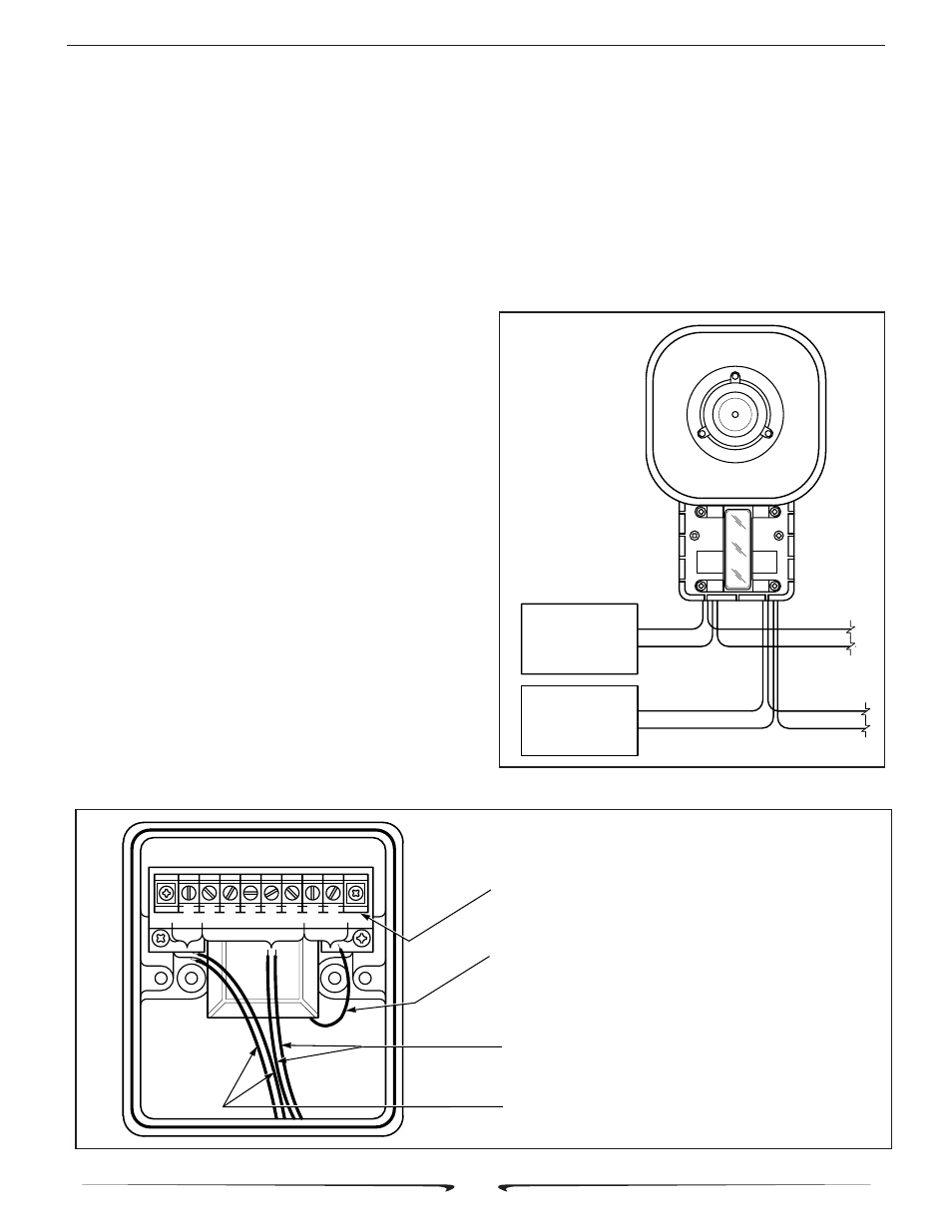
a.
See figure 2. Connect the strobe light’s red
(+) lead to the power source positive (+) lead. Connect the
strobe light’s black (-) lead to the power source negative (-
) lead.
WARNING
An uninsulated section of a single conductor must NOT be
looped around a terminal and used as two separate connec-
tions. NFPA 72 requires that the wire is severed to provide
electrical supervision of the connection. In addition, common
strobe leads must NOT be terminated within the same wire nut.
b.
See figures 2 and 3. Connect the audio
common (-) leads to the speaker’s common terminal and
audio positive (+) leads to desired wattage terminal.
c.
See figure 3. Connect the yellow lead,
found in the speaker, to the 25V or 70V terminal as
appropriate.
d.
Be sure the neoprene rubber cover gasket
is properly seated in the housing groove and reinstall the
housing cover.
IV. TESTING/OPERATING.
A. After installation is complete, be sure to test the
system to verify that each speaker and optional strobe light
operates satisfactorily. If it is found that the unit is too loud
for its location, a lower wattage tap may be selected.
Carefully remove the housing cover and move the positive
(+) lead to a lower wattage tap (see Figure 4). Reinstall the
housing cover and retest.
Figure 2. Typical Installation Wiring.
290B2627-07
RED
24 VDC
STROBE
POWER
BLK
+
-
RED
BLK
RED
BLK
RED
25 OR 75 VRMS
SPEAKER
SIGNAL SOURCE
BLK
+
-
Figure 3. Internal Multi-tap Wiring Set-up.
290A3355
NOTE: LETTERS APPEAR ON THIS SIDE OF TERMINAL STRIP. SHOWN
HERE ON MOUNTING BRACKET FOR REFERENCE ONLY.
SPEAKER INTERNAL YELLOW LEAD TO BE CONNECTED TO 25V OR 70V
TERMINAL, DEPENDING UPON EXTERNAL SIGNAL SOURCE VOLTAGE.
POSITIVE (+) LEADS TO 1 OF 5 AVAILABLE WATTAGE TERMINALS.
COMMON (-) LEADS TO COMMON TERMINAL
5W
1W
2W
7W
15W
25V
70V
YEL
COM