Harrington Signal SPHP-DVSMR User Manual
Page 2
- 2 -
256882
SPHP
Instruction Sheet
POWER
UL SOUND LEVEL
TAP
@ 10' dB(A)
0.5watt
87
1 watt
93
2 watt
96
7 watt
99
15 watt
102
Table 1. Power Tap Setting vs. Sound Output on
Model SPHP.
housing. Install supplied 1/2" conduit plug if only one 1/2"
conduit entrance is used.
WARNING
Property damage, serious injury or death could occur if the
projector is mishandled during installation or over time. DO
NOT rotate the projector more than 180 degrees or internal
speaker wiring may be damaged.
f.
Reposition speaker projector if necessary
to obtain desired sound coverage. Loosen collar nut (see
figure 1) and move projector to desired position.
g.
Before reinstalling the housing cover, read
paragraph III.C. Electrical Connections below and make the
necessary electrical connections.
2.
Concealed Conduit Moounting.
a.
Remove and retain the two screws that
secure cover to housing. Remove the cover.
b.
Remove the 7/8" knockout at rear of hous-
ing.
c.
Install the conduit connection.
NOTE
If installation on an existing electrical box is desired, an optional
Model CC adapter plate is required.
d.
Select the mounting location and place
rear of housing against mounting surface.
e.
Using the two (2) mounting holes as a
template, scribe drill position marks on the mounting sur-
face. See figure 1 for mounting hole locations and dimen-
sions.
CAUTION
Before drilling holes in any surface, ensure that both sides of
surface are clear of items that could be damaged.
f.
Secure the unit to a wooden mounting
surface with #10 x 1" wood screws. If mounting on a metal
surface, drill 13/64" diameter holes and secure the unit with
#10 screws, lockwashers and nuts.
WARNING
Property damage, serious injury or death could occur if the
projector is mishandled during installation or over time. DO
NOT rotate the projector more than 180 degrees or internal
speaker wiring may be damaged.
g.
Reposition speaker projector if necessary
to obtain desired sound coverage. Loosen collar nut (see
figure 1) and move projector to desired position. Install two
1/2" conduit plugs in the unused bottom entryways (one
plug supplied).
h.
Before reinstalling the housing cover, read
paragraph III.C. Electrical Connections below and make the
necessary electrical connections.
C.
Electrical Connections.
National Electrical Code as well as local codes
must be adhered to in installation of these models. All
electrical wiring must be routed through approved conduit
and fittings.
1.
Model SPHP (without Strobe Light Option).
a.
See figures 2 and 3. Connect the audio
common (-) leads to the speaker’s common terminal and
audio positive (+) leads to desired wattage terminal.
WARNING
An uninsulated section of a single conductor must NOT be
looped around a terminal and used as two separate connec-
tions. NFPA 72 requires that the wire is severed to provide
electrical supervision of the connection.
b.
See Figure 3. Connect the yellow lead,
found in the speaker, to the 25V or 70V terminal as
appropriate.
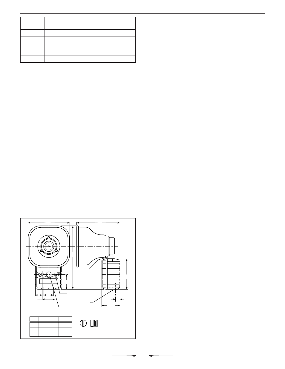
Figure 1. Model SPHP Speaker Dimensions.
290A2627-06A
A
C
B
1-13/16
.201 DIA. 2 HOLES
(MOUNTING)
2-9/16
7/8 DIA. CONCEALED CONDUIT KNOCK OUT
MOUNTING (IN REAR OF HOUSING)
2-3/4
COLLAR
NUT
2 x 1/2-14 NPT
5-5/8
13/16
3-3/8
INCHES
MM
A
B
C
206
302
203
8-1/8
11-7/8
8
1/2" CONDUIT PLUG
SUPPLIED
2