Harrington Signal IS815 User Manual
Page 2
2
3
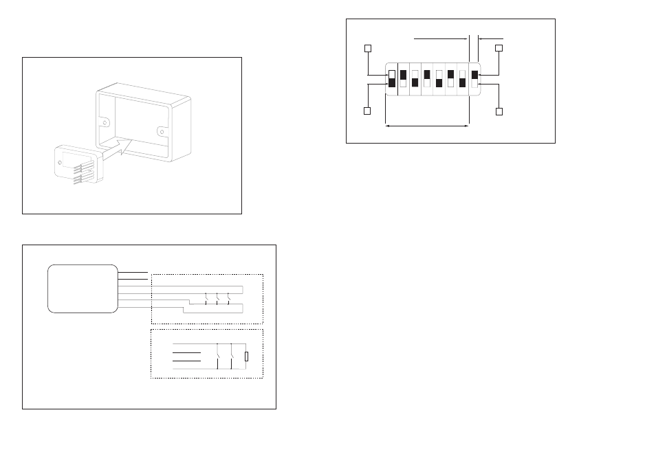
Address Setting
Segments 1–7 of the DIL switch are used to select the address of the module. Each of the
seven segments must be set to ‘0’ (ON) or ‘1’ (OFF) using a small screwdriver or similar
tool. A complete list of address settings is shown below. (The eighth segment of the switch
is used to select Class A or B wiring.)
DIL switch
DIL switch
DIL switch
DIL switch
DIL switch
addr setting
addr setting
addr setting
addr setting
addr setting
1234567
1234567
1234567
1234567
1234567
1 1000000
11 1101000
21 1010100
31 1111100
41 1001010
2 0100000
12 0011000
22 0110100
32 0000010
42 0101010
3 1100000
13 1011000
23 1110100
33 1000010
43 1101010
4 0010000
14 0111000
24 0001100
34 0100010
44 0011010
5 1010000
15 1111000
25 1001100
35 1100010
45 1011010
6 0110000
16 0000100
26 0101100
36 0010010
46 0111010
7 1110000
17 1000100
27 1101100
37 1010010
47 1111010
8 0001000
18 0100100
28 0011100
38 0110010
48 0000110
9 1001000
19 1100100
29 1011100
39 1110010
49 1000110
10 0101000
20 0010100
30 0111100
40 0001010
50 0100110
51 1100110
61 1011110
71 1110001
81 1000101
91 1101101
52 0010110
62 0111110
72 0001001
82 0100101
92 0011101
53 1010110
63 1111110
73 1001001
83 1100101
93 1011101
54 0110110
64 0000001
74 0101001
84 0010101
94 0111101
55 1110110
65 1000001
75 1101001
85 1010101
95 1111101
56 0001110
66 0100001
76 0011001
86 0110101
96 0000011
57 1001110
67 1100001
77 1011001
87 1110101
97 1000011
58 0101110
68 0010001
78 0111001
88 0001101
98 0100011
59 1101110
69 1010001
79 1111001
89 1001101
99 1100011
60 0011110
70 0110001
80 0000101
90 0101101
100 0010011
101 1010011
111 1111011
121 1001111
102 0110011
112 0000111
122 0101111
103 1110011
113 1000111
123 1101111
104 0001011
114 0100111
124 0011111
105 1001011
115 1100111
125 1011111
106 0101011
116 0010111
126 0111111
107 1101011
117 1010111
108 0011011
118 0110111
109 1011011
119 1110111
110 0111011
120 0001111
© Apollo Fire Detectors Limited 2004/JDR/JLC
Fig 1. Mounting the modules
RED
BLACK
YELLOW
GREEN
VIOLET
VIOLET
WHITE
YELLOW
GREEN
WHITE
47k
Ω
0.5W
EOL
I-SPY MINI SWITCH MONITOR
MODULE
© Apollo Fire Detectors LImited 2004/JDR/JLC
47k
Ω 0.5W EOL resistor connected internally across yellow and green wires
Class A wiring
Class B wiring
LINE 2*
LINE 1*
* Line 1 and Line 2 are polarity insensitive, but, for the sake of consistency it is recommended that Line 1 be kept negative.
Fig 2. Wiring Diagram for I-Spy Mini Switch Monitor and I-Spy Mini Priority
Switch Monitor Modules
Note
All circuits are power limited. Use only limited energy cable types FPL, FPLR or FPLP on
power limited circuits.
ON
1
5
4
3
2
64
32
16
8
4
2
1
7
6
0
1
A
B
WIRING CLASS
ADDRESS
© Apollo Fire Detectors Limited 2004/JDR
8
Fig 3. DIL Switch