Input card mx-ii, Tb1 tb2 – Harrington Signal HAVED-MP User Manual
Page 9
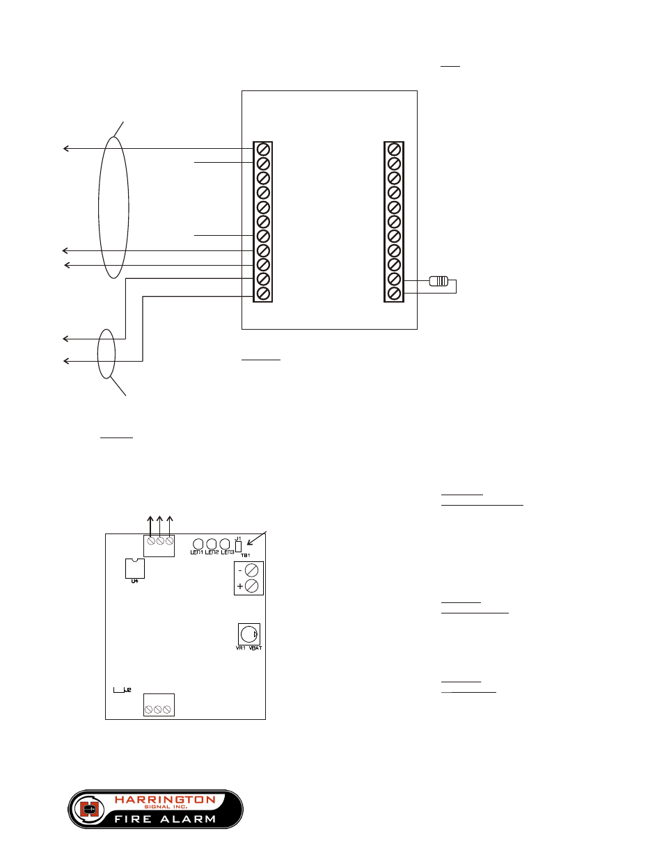
MX-II / PWR
Connection Detail
Terminal Designation
Wiring
FACP Bell Circuit - #18 AWG.
Input Control - #24 AWG.
(Must be in the same room within
20 feet of panel, in conduit)
IOI
1- 8 Input Control
(1mA 5VDC)
9 Circuit Common (NEG)
10 FACP Bell Circuit + (Alarm
11 FACP Bell Circuit - Polarity)
(10mA 24VDC)
MX-PWR
TB2
1 FACP EOLR
2 FACP EOLR
3 Circuit Common (NEG)
4-11 Input Control
(1mA 5VDC)
TB1
PWR
Input
Card
MX-II
TB1
TB2
To FACP Input Control
To FACP Bell Circuit
(24V 10mA min. rating)
Common
NEG
+
1
2
.
.
.
7
-
(N.O. Dry Contact)
8
End of Line Resistor
for FACP Bell Circuit
1
11
11
1
DCC
TB3
2 3 4
(Factory wired)
This wiring is Supervised by the FACP and
is Power Limited PROVIDED the FACP Bell
Circuit is Power Limited.
Non-Supervised - Power Limited
Supervised
Power Limited
In normal operation, FACP
will supervise system by
reading its EOLR. Under any
Fault condition in the HMX
system a contact will open
resulting in a Fault on the
FACP bell circuit.
**ALARM Polarity shown**
1
1
2
2
3
3
jumper J1
remove before connecting batteries
P/N HS-5010 REV. C
page 9 of 12
TB1:
Ter. 1 & 2
battery connections
1- circuit negative
2-+24VDC
max charging current: 1A
max reccomended battery
size: 18ah
TS1:
Ter. 1,2,3
+24 VDC output
1-fault report output
2-+24 VDC
3-circuit negative
TS2:
Ter. 1,2,3
28 VAC input
1,2 - 28 VAC in
3 - ground fault detect,
to chassis
(optional- if
unit mounted with snap
track, connection is necessary.
If metal standoff used in lower
left corner, connection is not
necessary)
TS-1
TS-2
2519 Fourth Avenue
Moline, IL 61265
(800) 577-5758 (v)
(309) 762-8215 (f)
www.harringtonfire.com