Elevator linkage installation – E-flite BAe Hawk 15 DF ARF User Manual
Page 19
19
E-flite BAe Hawk ARF Assembly Manual
13. Break in the elevator hinges by moving the
elevator through its range of motion a few times.
This will help in reducing the initial load on the
servo and make the control surfaces easier to
move initially.
14. Repeat Steps 5 through 13 to install the
remaining elevator.
Elevator Linkage Installation
Required Parts
Assembled airframe
Elevator control horn (2)
Elevator pushrod keeper (2)
Elevator pushrod wire, 24
7
/
16
-inch (620mm) (2)
Required Tools and Adhesives
Hobby knife w/#11 blade
Needle-nose pliers Medium CA
1. Slide the elevator pushrod tube back into
position in the fuselage. When the pushrod is in
the correct position it will be at the very bottom
of the slot in the former.
2. Tack the pushrod into position on the former with
medium CA as you might need to break it loose if
maintenance is required to the fan and motor.
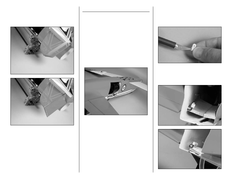
3. Use a hobby knife to make a slight bevel inside
the hole of the elevator control horn. Rotate the
hobby knife like a drill to make the bevel even. This
will help when installing the control horn onto the
elevator control horn wire.
4. Thread the elevator control horn onto the
elevator control horn wire. The end of each control
horn will be flush with the end of the wire as shown
in the photo.