Dynalite RR-GH User Manual
Page 2
Grid Holder & Grid Set Instructions
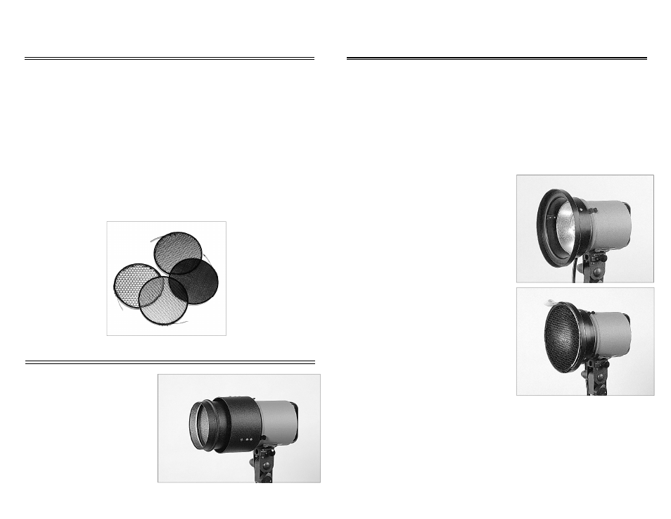
Your new Grid Set will add another dimension of light control to your Dynalite system.
The Grid Set consists of four grids per set: one set 10º, 20º, 30º, 40º, in black. The
grids will provide a basic spot light effect and will have a sharp fall-off light pattern.
The Grid Holder is the interface between the grids and your Dynalite RH-1050 and
MH2050 flash head. The SR-65 on your SH2000 and SH4080 flash heads also dou-
bles as a 7” grid holder as well. Gels can also be used in the RR-GH grid holder and
the SR-65 reflector. Additionally, Comet grids, or any other 7” grid can be used in the
Dynalite Grid Holder.
Instructions:
Dynalite Grids are simple to use and require no
special instruction. They snap into the Dynalite
RR-GH grid holder or SR-65 reflector. To use the
Dynalite Grids follow this procedure:
1. Disconnect the flash head from the power
pack.
2. Install the Dynalite Grid Holder (RR-GH) on
flash head. NOTE: Make sure the three (3)
spring clips on the grid holder are on the
accessory ring.
3. Select the grid of your choice and gently
press the grid (RR-4G) into the grid holder.
4. To change or remove the grid, pull the at-
tached Teflon tab.
5. To remove the Holder or Angle Reducing
Ring, let unit cool, then push the spring clips
up and over the accessory ring from the
back.
Packing and Storing:
Do not pack this or any accessory that is still hot to the touch. Hot accessories should
be allowed to cool prior to packing or storing
.
Use As Gel Holder:
To use various color gels, you must cut the gel material to fit into the grid adapter or
reflector. Trace the grid adapter on high temp gel material such as Roscolux Gel Mate-
rial or equivalent. Cut out the round gel and insert it between the grid and the grid
holder.
Important Safeguards
Please take a moment to read these safety precautions and instructions. Spending
a few moments now will ensure years of use in the future.
1 Read and understand all instructions.
2 Care must be taken as burns could occur from touching the modeling lamp(s)
or flash tube(s).
3 Do not install or remove any accessory until the flash head is disconnected
from power pack.
4 Allow flash heads and accessories to cool completely before storing or removing
accessories or flash head.
5 Do not let cords or cables hang on or touch hot accessories or surfaces.
Please save these instructions so that all users may read this information
Angle Reducing Ring
The angle reducing ring allows you to
reduce the angle of coverage from
140º to 60º for the RH1050, MH2050
series flash heads. The quality of light
will be similar to the flash heads’ built-
in reflector and will retain the “hard
edge” look.* To install, simply follow
the instructions for the grid holder on
the next page.