Burnham E4 User Manual
Page 3
3
A.
Inspect Shipment carefully for any signs of damage.
1. All equipment is carefully manufactured, inspected
and packed. Our responsibility ceases upon delivery
of Boiler to the carrier in good condition.
2. Any claims for damage or shortage in shipment
must be fi led immediately against the carrier by
the consignee. No claims for variances from,
or shortage in orders, will be allowed by Boiler
Manufacturer, unless presented within sixty (60)
days after receipt of goods.
B.
Read These Instructions Carefully before proceeding
with installation and operation of the “CARE-FREE”
Electric Boiler.
1. The “CARE-FREE” is U.L. listed, constructed
and tested in accordance with the requirements of
the ASME Boiler and Pressure Vessel Code and
designed for use in any conventional hydronic
system except steam and gravity hot water.
2. The “CARE-FREE” Electric Boilers are shipped
completely assembled less circulator. All electrical
controls are mounted and wired in a compartment
immediately behind the Front Door of the Boiler
Jacket, see Figure 1.
C.
Locate Boiler in or adjacent to the space to be heated
with consideration given to the location of the electrical
service. Although its compactness will allow the
“CARE-FREE” Electric Boiler to be mounted almost
anywhere – closet, alcove, or other small area, see
CLEARANCE REQUIREMENTS on Page 2.
D.
Mount Boiler to wall using four 3/8" lag screws
or anchor bolts (depending upon wall construction)
passing through the holes provided in the wall
mounting channels. Figure 1 shows bolt center
dimensions. It is recommended that 1/2" plywood
be used as a base for mounting the boiler so that the
structure is adequate to carry the weight imposed upon
it – see Figure 1 for weight of boiler when full of water.
Boiler should be level for proper operation of BUILT-
IN AIR SEPARATOR.
E.
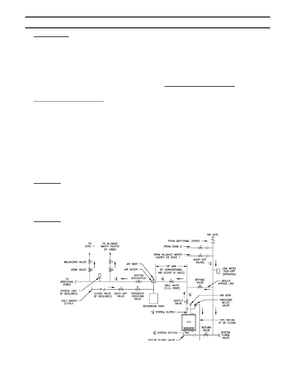
Connect Supply and Return Piping to Heating
System using standard recognized practices. See Figure
2. Install an appropriate size expansion tank in system
as per Figure 2. Do not connect into the 3/4" tee on top
of the boiler; instead install an automatic fl oat type air
vent at this point. Water content of the boiler is given
in Figure 1.
The relief valve outlet should be piped full size to a
drain or near the fl oor.
The heating elements are NOT compatible with
ethylene glycol based antifreeze.
If a low water cut-off is required, it must be mounted in
the system piping above the boiler.
The minimum safe water level of a hot water boiler is
just above the highest water containing cavity of the
boiler; that is, a hot water boiler must be full of water to
operate safely.
If it is required to perform a long term pressure test of
the hydronic system, the boiler should fi rst e isolated to
avoid a pressure test including the boiler, ALL trapped
air must fi rst be removed from the boiler.
A loss of pressure during such a test, with no visible
water leakage, is an indication that the boiler contained
trapped air.
SECTION I: INSTALLATION INSTRUCTIONS
Figure 2: Recommended Boiler Piping