Clay Paky ATLAS (HMI 575) User Manual
Page 3
7
250 V
10AT
5 x 20
FUSE
POSSIBLE REASONS
CHECKS & REMEDIES
TROUBLESHOOTING
6
No mains power supply.
Check that power is reaching the
supply socket and/or that the fuses
are not blown.
THE PROJECTOR WILL NOT START UP
THE ELECTRONICS ARE INOPERABLE
DEFECTIVE PROJECTION
REDUCED LIGHTING
•
•
•
•
•
•
•
Light bulb blown or defective.
Replace the bulb
(see instructions).
Signal transmission cable short-
circuited or disconnected.
Replace the cables.
Incorrect coding.
Check the coding
(see instructions).
Fault in the electronic circuits.
Broken lenses.
Contact an authorised technician.
Contact an authorised technician.
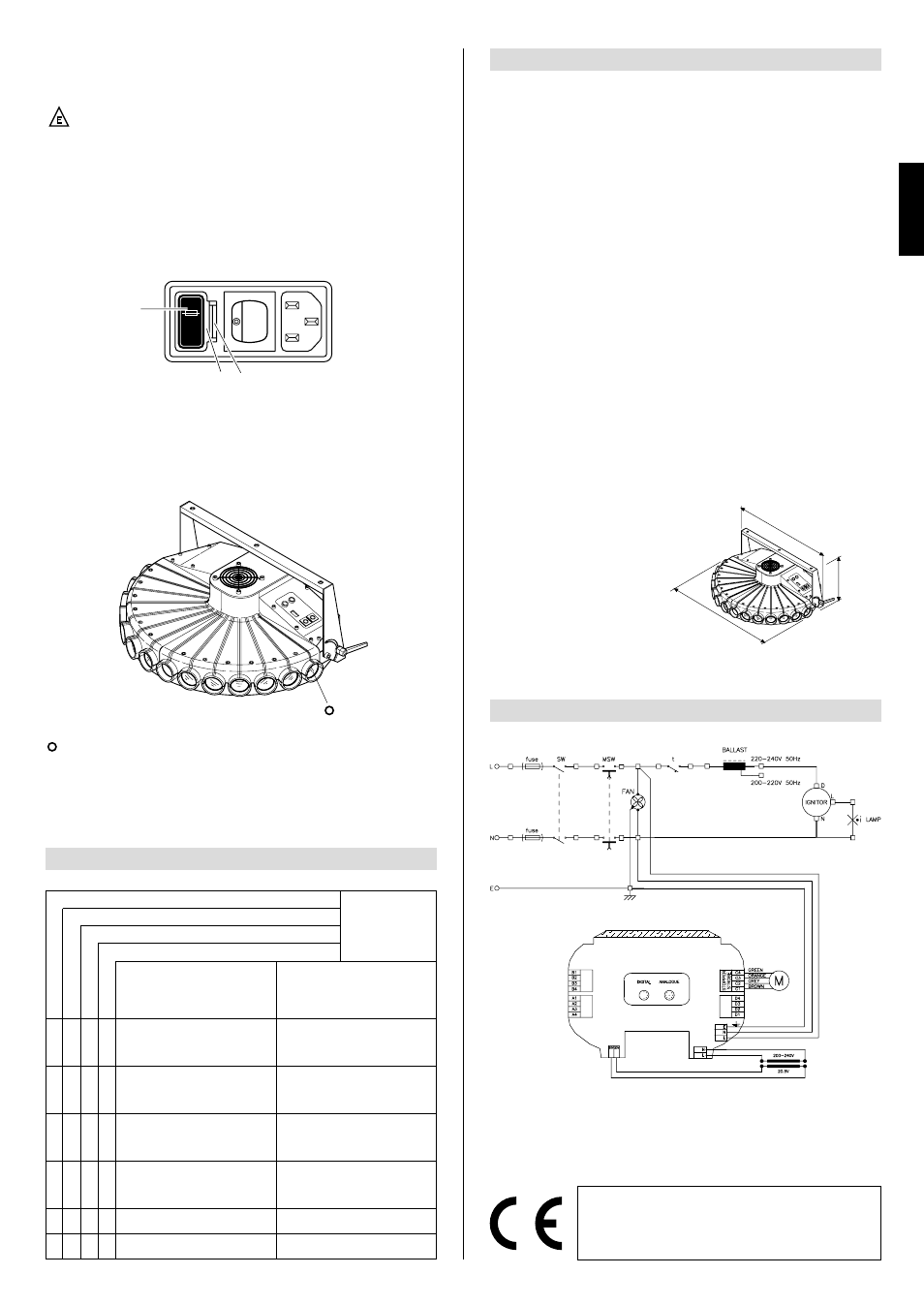
TECHNICAL DATA
CONSTRUCTIONAL DETAILS
Devices
• Automatic power supply cut-off in
the case of overheating or a cooling
system breakdown.
• Automatic power supply cut-off
when the cover is opened.
Cooling
Forced ventilation cooling system
using axial fans.
Body
• Of diecast extruded aluminium
• Painted with epoxy powders
Stand
Made of steel painted with epoxy pow-
ders
Work position
It will operate in any position.
Weights and size
Weight: 27 kg (59 lbs 6 ozs)
ELECTRICAL
& MECHANICAL DETAILS
Power supplies available
• 220 - 240V 50Hz
• 200 - 220V 60Hz
• 200V 50Hz
• 200V 60Hz
• 260V 50Hz
The projector is designed to operate
at the mains frequency and voltage
given on the electrical data label on
the base of the appliance.
Light bulb
Metal iodides fed by a special incor-
porated power supply unit.
• Type HMI 575W
– Cap SFc 10-4
– Colour temperature 5600 K
– Light flux 49000 lm
– Average life 750 h
Power absorbed
1500 VA at 220V 50Hz
Motors
N. 1 step-by-step motor, operating in
microsteps and totally controlled by a
microprocessor.
COMMAND SYSTEMS
Channels
N. 1 control channel
Inputs
ATLAS is designed to analogue or
digital control signals transmitted
from control units or computers.
• Serial digital input
RS232/423(PMX) or DMX 512
• Analogue input 0 - 10V
7
ENGLISH
FAULTS
The products to which this manual refer comply with the
following European Union Directives:
• Low Voltage 73/23
• Electromagnetic Compatibility 89/836
WIRING DIAGRAM
With the desire to constantly improve the quality of its products, Clay Paky reserves the
right to change the specifications mentioned in this document without prior notice. Thus
they should not be taken as binding.
8
• Fuse replacement
To replace the fuses, press tongue (19) and remove fuse box (20).
Replace the blown fuses with new ones of the type shown on label (21) located on
fuse box (20).
Return this by pushing it in until tongue (19) clicks.
• Periodic maintenance
Periodic cleaning of the parts subject to dust and grease deposits is indispensable
for keeping the projector's light yield unchanged.
Perfect operation can be ensured for a long time by following the directions given
below.
Use a soft cloth dampened with a liquid detergent for cleaning glass to remove dirt
from the lenses and filters.
IMPORTANT: do not use solvents or alcohol.
Parts that need frequent cleaning.
An annual general cleaning of the inside is also recommended, removing the dust
with a brush and sucking it out with a normal vacuum cleaner.
IMPORTANT: to ensure maximum uniformity of the light beams, the light bulb must
be located with protuberance (18), visible on the bulb, pointing towards the rear of
the projector.
CAUTION: The appliance is fitted with a high pressure light bulb with an
external starter.
- Carefully read the “User Instructions” provided by the light bulb's manufacturer.
- Replace the light bulb immediately if it is damaged or warped by heat.
19
20
21
(24.8”)
630
(15.7”)
400
(28.5”)
725