Channel function, Lens, Maintenance – Clay Paky ATLAS (HMI 575) User Manual
Page 2
6
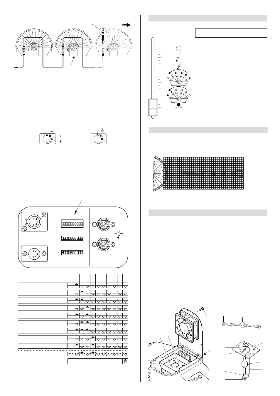
CHANNEL FUNCTION
3
• STOP/STROBE - channel 1
With the cursor at 0% all bands are
obscured. In the cursor interval
between 0% and 25% the bands are
progressively opened from right to
left, creating a fan effect. From 25%
to 54.7% the bands are progressive-
ly obscured from right to left. From
54.7% to 95% a strobe effect is
obtained with an increasing frequen-
cy from 1 flash every four seconds
to 2 flashes/second. The aperture is
fixed from 95% to 100%.
CHANNEL
1
STOP/STROBE
FUNCTION
0
1
2
3
4
5
6
7
8
9
10
The connection between projector and control unit and between several projectors
must be made with a shielded two-pole cable with Cannon 5 PIN XLR plug and
socket at the ends.
For DMX connection the terminal pin (6) with a resistance of 100
Ω
between ter-
minals 2 and 3 on the last projector. The terminal is not needed if an
RS232/423(PMX) signal is used.
It is essential that the wires do not come into contact with each other or with
the metal casing of the pin.
The casing of the plug/socket must be connected to the screen braid and to
foot 1 of the connectors.
After having performed all the operations described above, press switch (7) and
check that the light bulb switches on and that the automatic reset sequence starts.
• Projector coding (for digital signals)
Each ATLAS occupies one control channel. For this to be correctly addressed to each
projector, a coding operation must be performed for the projectors themselves. The
operation must be performed for each single ATLAS by setting the microswitches
according to the table below.
Setting the TEST switch to ON for a few seconds gives automatic reset with the pro-
jector switched on. Leaving the TEST switch ON gives the complete self-test; return
the switch to OFF at the end of the operation.
SIGNAL
SCREEN
SIGNAL
RS232/423
(PMX)
1
2
3
4
5
SIGNAL
SCREEN
SIGNAL
5
4
3
2
1
DMX
512
LENS
4
1
0
BEAM OPENING
m
0
5
10
15
20
25
30
35
40
DISTANCE m
0
0,1
0,14
0,18
0,22
0,26
0,30
0,34
0,38
DIAMETER m
1
HMI 575
6400
1600
710
400
256
177
130
100
lux
0”
16’ 5”
DISTANCE ft in
32’ 10”
49’ 3”
65’ 7”
82’
98’ 5” 114’ 10” 131’ 3”
0”
4”
DIAMETER ft in
6”
7”
9”
10”
12”
1’ 1”
1’ 3”
595
149
66.0
37.2
23.8
16.4
12.1
9.29
fc
LIGHT BAND AND LIGHTING VALUE DIAGRAMS
Beam angle (0,5°)
MAINTENANCE
5
TEST
256
128
64
32
16
8
4
2
1
ON
10
9
8
7
6
5
4
3
2
1
DIGITAL INPUT
DIP
ANALOGUE INPUTS
STOP
Is
0-10V
Projector
4
- Channels
4
Projector
5
- Channels 5
Projector
6
- Channels
6
Projector
7
- Channels
7
Projector
8
- Channels
8
Projector
9
- Channels
9
Projector
10
- Channels
10
Projector
3
- Channels
3
Projector
2
- Channels
2
Projector
1
- Channels 1
ON
OFF
ON
OFF
ON
OFF
ON
OFF
ON
OFF
ON
OFF
ON
OFF
ON
OFF
1
2
4
8
16
32
64
128
256
TEST
OFF
ON
OFF
ON
OFF
ON
CODE
IMPORTANT: the projector must be disconnected from the power supply before any
operation is started.
The maximum temperature of the appliance's outer surface in heat regime conditions
is 80° C (176° F). After switching off, do not remove any part of the appliance for 7
minutes, as shown in light bulb changing label (1).
After this time the probability of the bulb exploding is virtually nil.
If necessary, replace the bulb and wait a further 15 minutes to prevent burns. The
appliance is designed to retain splinters produced by a possible explosion of the bulb.
It is mandatory to fit the lenses and moreover, if they show visible signs of damage
they must be replaced with original spare parts.
• Light bulb changing
Remove screws (8) and open fan hatch (9).
Unscrew knobs (10) of light bulb change plate (11) and remove it from the projector.
Slacken off ring-nut (12) of the light bulb to be replaced and remove it from plate (13),
grasping it by its mount (14). Extract the new bulb from its pack, remove ring-nut (15)
and slacken of the other one (12). Screw the light bulb directly into bulb change plate
(13), grasping it by its mount (14). Position strip (16) in correspondence with mount
(17) and fully tighten ring-nut (12). Replace light bulb change plate (11) in the projec-
tor and tighten knobs (10). Close fan hatch (9) and fully tighten screws (8).
RS 232-423
DMX 512
RS 232/423(PMX) - DMX 512
7
6
18
15
12
8
9
1
11
10
13
14
17
12
16
11
18
Spotlight selection