Bunn CRTF5 User Manual
Page 20
Page 20
SERVICE (cont.)
TANK HEATER
Location:
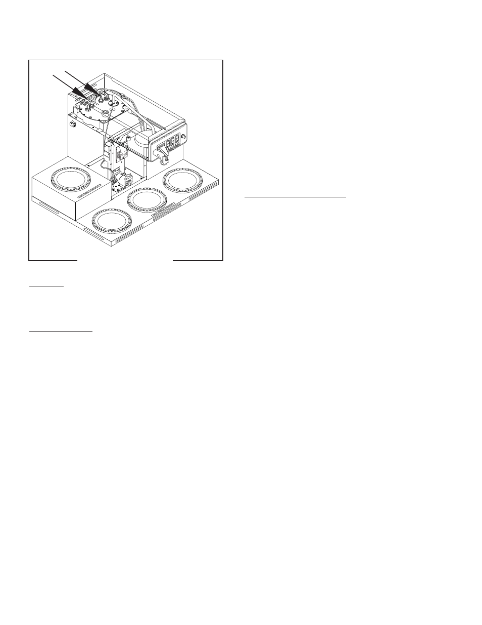
The tank heater is located inside the tank and
secured to the tank lid.
Test Procedures:
1. Disconnect the brewer from the power supply.
2. Check the voltage across the black and white wires
on 120 volt models or the black and red wires for
120/240 volt models, 200 volt models and 240
volt models with a voltmeter. Connect the brew to
the power source. The indication must be:
a) 120 volts ac for two wire 120 volt 20 amp
models .
b) 240 volts ac for three wire 120/240 volt models.
c) 200 to 240 volts ac for two wire 200 or 240 volt
models.
3. Disconnect the brewer from the power source.
If voltage is present as described, proceed to #4
If voltage is not present as described, refer to the
Wiring Diagrams
and check wiring harness.
4. Disconnect the black wire and the white wire or red
P2186.45
FIG. 12 TANK HEATER
wire from the tank heater terminals.
5. Check for continuity across the tank heater termi-
nals.
If continuity is present as described, reconnect the
wires, the tank heater is operating properly.
If continuity is not present as described, replace the
tank heater.
NOTE- If the tank heater remains unable to heat,
remove and inspect heater for cracks in the sheath.
Removal and Replacement:
1. Disconnect the water supply tube from the fill
basin.
2. Remove the tank inlet fitting securing the fill basin
to the tank lid, remove fill basin and tank inlet
gasket. Set all three parts aside for reassembly.
3. On brewers with faucet shut-off water supply to
the brewer and disconnect the inlet and outlet
water lines to the faucet coil assembly.
4. Disconnect the black wire on the limit thermostat
from the tank heater switch. On late model brew-
ers also disconnect the blue wire from the limit
thermostat to the control thermostat.
5. Disconnect the black wire and the white or red wire
from the tank heater terminals.
6. Remove sprayhead and the hex nut securing the
sprayhead tube to the hood. Set aside for reas-
sembly.
7. Remove the eight #8-32 nuts securing the tank lid
to the tank.
8. Remove the tank lid with limit thermostat, spray-
head tube, tank heater, coil assembly and control
thermostat w/bracket (early models only).
9
Remove the two hex nuts securing the tank heater
to the tank lid. Remove tank heater with gaskets
and discard.
10. Install new tank heater with gaskets on the tank lid
and secure with two hex nuts.
11. Install tank lid with limit thermostat, sprayhead
tube, tank heater, coil assembly (brewers with
faucet) and control thermostat with bracket (early
brewers only) using eight #8-32 hex nut.
12. Reconnect the inlet and outlet water lines to the
faucet coil assembly.
10478 061500