Operating instructions, Page 5 – Blizzard Lighting Skyline User Manual
Page 5
Page 5
Skyline™ User Manual - Rev. A
(c) 2014 Blizzard Lighting, LLC
Rear Side
9.) Power Input
AC Power Cable Input
10.) DMX IN A/B
DMX Signal Inputs
11.) DMX Thru Out A/B
DMX Thru Signal Outputs
12.) Power Switch
Power On/Off
13.) Antenna Terminal
To Mount the Antenna
14.) Terminator Resistor Switch
DMX Signal Termination
3. OPERATING INSTRUCTIONS
The DMX splitter is designed to distribute and boost the incoming DMX signal into each of its 8
separate outputs. Each of the 8 outputs is electronically isolated from the others (with the exception
of the “thru” outputs), and each output has 3-pin DMX sockets. Each output has dedicated drivers
to boost the incoming signal. This greatly decreases problems with ground loops and efficiently
buffers while magnifying the DMX signal, making it more accurate and reliable.
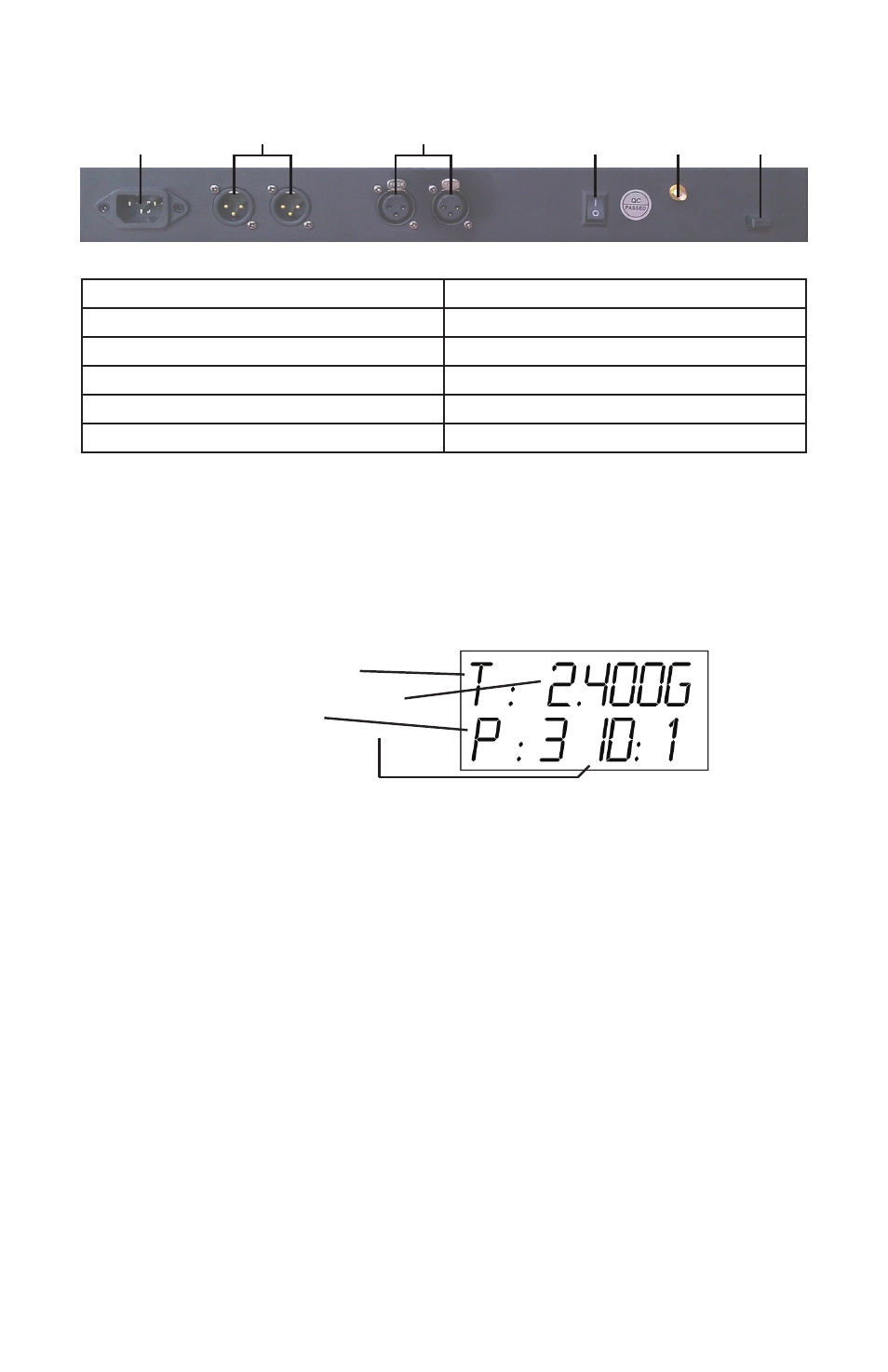
The LCD display onboard the Skyline™ Wireless DMX transceiver gives you all pertinent information
about the unit’s operating mode. Below, each symbol is described:
1.) Operation Mode: Mode of the unit, either Transmitter (“T”), Receiver (“R”), or Searching (“-”).
2.) Operating Frequency: Displays the current operating frequency while the unit is in Transmit-
ter or Receiver Mode. While in Searching mode, the unit will display the current frequency being
scanned.
3.) Transmission Power Level: Displays the current transmission power (applicable for Transmit-
ter Mode Only):
• “0” = 2dBm (Lowest)
• “1” = 8dBm
• “2” = 14 dBm
• “3” = 20 dBm (Highest)
To change the transmission power level, use the “PA” button located on the front panel.
4.) Channel Group ID: Displays the current channel group (0-9, A-F). In auto mode, the trans-
mitting unit will auto-select the clearest channel group. When a receiving unit in a single-group
setup is powered on, it will automatically sync to the transmitter. In multiple transmitter/receiver
setups, manual configuration may be required.
To manually configure the channel group ID, use the “ID” button on the front panel. Set each
transmitter/receiver group to the same group ID to ensure correct operation.
9
10
11
12
13
14
Operation Mode (1)
Operating Frequency (2)
Power Level (3)
Channel Group ID (4)