Bendix Commercial Vehicle Systems TRDU User Manual
Installation instructions, Bendix, Trdu
Installation
Instructions
1
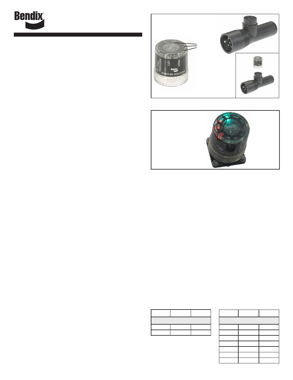
LED lights
illuminate
Diagnostic
Trouble
Codes
(10 locations
in total)
BENDIX
®
TRDU
™
TRAILER REMOTE
DIAGNOSTIC UNIT
The Bendix
®
TRDU
™
(Trailer Remote Diagnostic Unit) is a diagnostic
tool providing the technician with a visual indication of component
Diagnostic Trouble Code (DTC) information from Bendix
®
Antilock
Brake Systems (ABS) for trailers. The TRDU
™
unit communicates
across PLC4Trucks supporting common diagnostic messages.
Additionally, the Bendix
®
TRDU
™
provides odometer mileage readout,
a method for clearing the ABS component Diagnostic Trouble Codes,
and allows the user to self-configure the ABS ECU configuration on
Bendix
®
TABS-6, and MC-30
™
with PLC ECUs. It will also clear most
A-18
™
ABS with PLC ECUs (in this case, certain sensor DTCs require
the vehicle to be driven).
The TRDU
™
unit is specifically designed for use with Bendix
®
ABS and
although Bendix has included some competitive support, based on
reading some standard diagnostic messages, Bendix makes no claims
for its operation and/or usability with other brands of ABS systems.
DEVICE FEATURES
The TRDU
™
unit attaches to the main trailer electrical connector
(SAE J560) located at the nose of the trailer by using a 7 to 7 pin
adapter (802165).
The TRDU
™
tool allows the technician to:
• Troubleshoot ABS system component problems using Diagnostic
Trouble Code reporting via LEDs. Blink codes are also activated
when the TRDU
™
unit is first attached to trailers with a TABS-6
ECU (the full readout is displayed using the trailer-mounted ABS
lamp).
• Reset the Diagnostic Trouble Codes on Bendix
®
ABS ECUs by
holding a magnet over the “B” of the Bendix logo on the face of
the TRDU
™
tool for 6, or less, seconds.
• Enter the Self-Configuration Mode for MC-30 and TABS-6 standard
& premium models by holding a magnet over the reset area for
greater than 6 seconds but less than 11 seconds. Note that, in
the case of TABS-6 advanced ECUs, to enter the self-configuring
mode a connected PC with Bendix
®
ACom
®
Diagnostics Software
is required.
• Read the odometer data. This information is continuously flashed
out using the TRDU
™
unit’s ODO LED as soon as communications
is established, and repeats every 10 seconds.
OPERATION
When the TRDU
™
unit is plugged in and receiving power (through
the adapter), all the LEDs will illuminate for one half-second, and the
green LED VLT will flash 4 times to indicate communications have
been established. The blue ODO LED will immediately begin blinking
out the odometer reading from the trailer ABS ECU, and continue
blinking odometer reading out every 10 seconds.
• If the ABS ECU has no active Diagnostic Trouble Code(s), only
the green LED will remain illuminated.
• If the ABS ECU has at least one active Diagnostic Trouble Code
the TRDU
™
tool displays the first Diagnostic Trouble Code by
illuminating the red LEDs, indicating the malfunctioning ABS
component and its location on the vehicle.
• If there are multiple Diagnostic Trouble Codes on the ABS system,
the TRDU
™
unit will display one Diagnostic Trouble Code at a time,
then after the first Diagnostic Trouble Code has been repaired and
cleared, the next code will be displayed.
FIGURE 1 - THE BENDIX
®
TRAILER REMOTE DIAGNOSTIC
UNIT AND ADAPTER
Patents Pending
Left
Additional
Sensor
DTC
For example, if
the Diagnostic
Trouble Code is
Left
Additional Sensor,
the TRDU will display
the Diagnostic Trouble
Code as shown.
FIGURE 2 - EXAMPLE OF A DIAGNOSTIC TROUBLE CODE
TYPICAL LED ALERTS ARE:
Right sensor (RHT + SEN), Left sensor (LFT + SEN), Right additional
sensor (RHT + ADD + SEN), Left additional sensor (LFT + ADD +
SEN), Modulator 1 (M1), Modulator 2 (M2), Modulator 3 (M3), ECU,
VLT (Flashing indicates either over or under voltage condition), All
LEDs in a circular pattern = no communication.
To pinpoint the root cause and to ensure the system Diagnostic Trouble
Code is properly corrected the first time, additional troubleshooting
may be necessary.
For more information on troubleshooting and repairing Bendix ABS
Diagnostic Trouble Codes, download the ABS service data sheet from
www.bendix.com, or order paper copies from the Literature Center
at bendix.com.
ABS Controller
Service Data Sheet
A-18
™
Controller . . . . . . SD13-4757 (order BW2262)
MC-30
™
Controller . . . . . SD13-4834 (order BW2189)
TABS-6
™
Stnd. & Prem. Controller SD13-4767 (order BW2469)
TABS-6
™
Adv. Single Channel . . SD13-47671 (order BW2718)
TABS-6
™
Adv. Multi Channel . . SD13-47672 (order BW2726)
For other ABS manufacturer’s ECUs, obtain the appropriate service
information from the ABS manufacturer. In some cases, the following
chart may assist the technician when troubleshooting certain systems:
TRDU
Wabco*
Haldex**
2S/1M Systems
SEN
YE1
S1A
ADD
YE2
S1B
TRDU
Wabco*
Haldex**
4S Systems
SEN
YE1
S3A
ADD
YE2
S3B
LFT
BU1
S2A
RHT
BU2
S2B
M1
Red
Red
M2
Yellow
Yellow
M3
Blue
Blue
* Trademark of WABCO
** Trademark of HALDEX AB