Bendix Commercial Vehicle Systems RDU User Manual
Installation instructions, Bendix, Remote diagnostic unit
Installation
Instructions
1
BENDIX
®
RDU
™
REMOTE DIAGNOSTIC UNIT
The Bendix
®
RDU
™
(Remote Diagnostic Unit) is a diagnostic
tool providing the technician with a visual indication of Antilock
Braking System (ABS) component Diagnostic Trouble Code
(DTC) information. The RDU
™
unit can be used on Bendix
®
ABS-equipped semi-tractors, straight trucks, coaches, and
buses. Additionally, the RDU
™
unit provides a method for
clearing the ABS component diagnostic trouble codes from
Bendix
®
ABS controllers and allows the technician to self-
configure the ABS ECU on Bendix
®
EC-17
™
, EC-30
™
, and
EC-60
™
ABS controller ECUs.
The RDU
™
unit is specifically designed for use with Bendix
®
ABS and Bendix makes no claims for its operation and/or
usability with other brands of ABS systems.
DEVICE FEATURES
The RDU
™
remote diagnostic unit attaches to the 9 pin
diagnostic connector in the cab of the vehicle. An adapter
cable (Bendix part number 801872) is available to connect
the RDU
™
tool to vehicles with a 6-pin diagnostic connector.
The RDU
™
tool allows the technician to:
•
Troubleshoot ABS system component problems using
Diagnostic Trouble Code reporting via LEDs.
•
Reset Diagnostic Trouble Codes on Bendix
®
ABS ECUs
by holding a magnet over the reset in center of RDU
™
tool
for less than 6 seconds.
•
Enter the Self-Configuration Mode used by Bendix
®
ABS
ECUs by holding a magnet over the reset area for greater
than 6 seconds but less than 30 seconds.
OPERATION
See Figure 2 for typical vehicle connector locations.
When the RDU
™
unit is plugged into the diagnostic connector,
all the LEDs will illuminate, and the green LED will flash 4
times to indicate communications have been established.
If the ABS ECU has no active Diagnostic Trouble Codes,
only the green LED will remain illuminated.
If the ABS ECU has at least one active Diagnostic Trouble
Code the RDU
™
tool displays the first diagnostic trouble code
by illuminating the red LEDs, indicating the malfunctioning
ABS component and its location on the vehicle. (See Figure
3.) If there are multiple diagnostic trouble codes on the ABS
system, the RDU will display one diagnostic trouble code
first, then once that Diagnostic Trouble Code has been
repaired and cleared, the next code will be displayed.
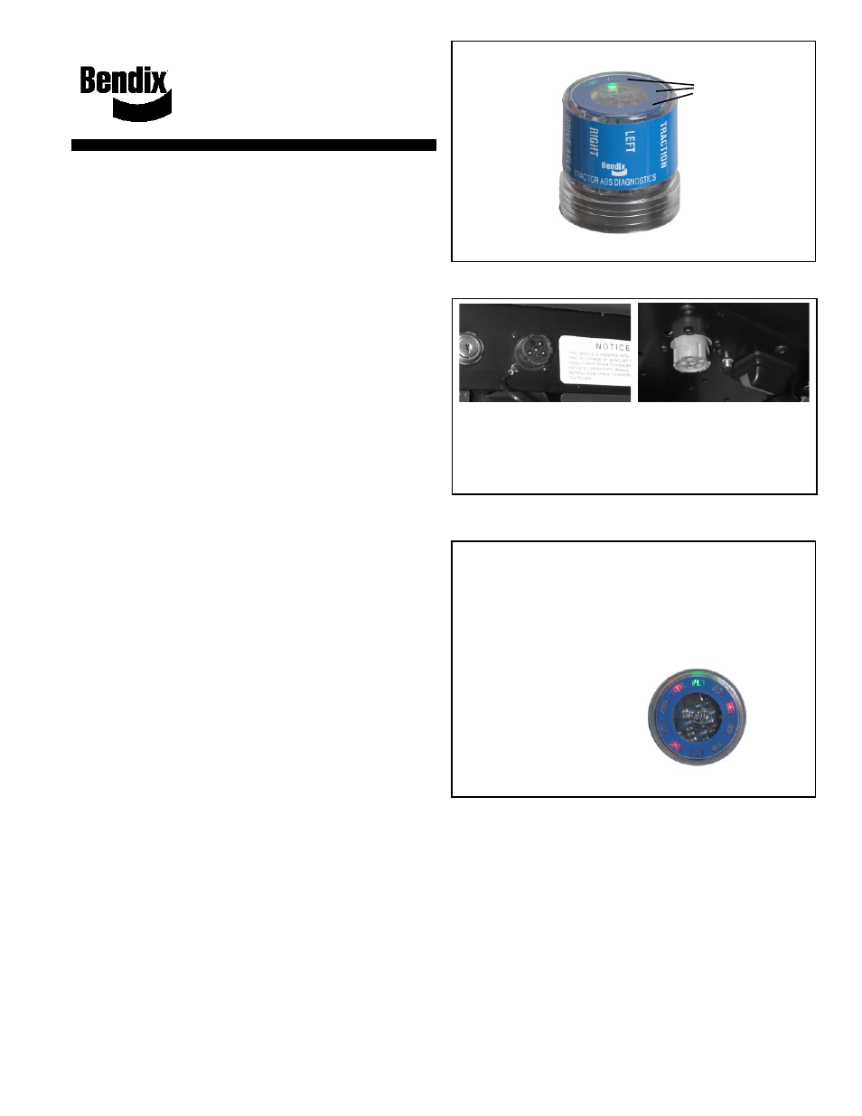
FIGURE 1 - THE BENDIX
®
REMOTE DIAGNOSTIC UNIT
LED lights
illuminate
Diagnostic
Trouble
Codes
(10 locations
in total)
LED Diagnostic Trouble Codes
LFT -
Left
RHT -
Right
DRV -
Drive Axle
ADD -
Additional
STR -
Steer Axle
VLT -
Power
ECU -
ABS Controller
SEN -
Wheel Speed
Sensor
MOD -
Pressure Modulator
Valve
TRC -
Traction Control
FIGURE 3 - DIAGNOSTIC TROUBLE CODES
FIGURE 2 - TYPICAL VEHICLE DIAGNOSTIC
CONNECTOR LOCATIONS (J1708/J1587, J1939)
Located on
Dash Panel
Located Under
Dash Panel
Or
(Note: An adapter is required when the vehicle
has a 6-pin connector.)
Typical Combination Diagnostic Trouble Codes are:
•
Right steer sensor
•
Left steer sensor
•
Right drive sensor
•
Left drive sensor
•
Right additional sensor
•
Left additional sensor
•
Right steer modulator
•
Left steer modulator
•
Right drive modulator
•
Left drive modulator
•
Right additional modulator
•
Left additional modulator
•
Traction modulator
•
ECU
•
Engine serial
communication
Patents Pending
Example: If the Diagnostic
Trouble Code is "Right
Steer Axle Sensor", the
RDU
™
unit will display one
green and three red LEDs
LEDs
Green
VLT
Red
SEN
STR
RHT