Bendix Commercial Vehicle Systems M-40HF PMV SD User Manual
Page 3
3
PRESSURE MODULATOR VALVE (PMV) AND
TRACTION CONTROL VALVE (TCV) CHUFF TEST
A wiring harness connects the vehicle modulators to the
controller. The ABS controller is able to simultaneously,
and independently, control the individual modulators.
Bendix
®
Electronic Control Units (ECUs) perform a Bendix-
patented PMV and TCV Chuff Test. The Chuff Test is
an electrical and pneumatic PMV test that can assist
maintenance personnel in verifying proper PMV wiring and
installation. This test is performed only when the vehicle
is stationary (if the vehicle moves, the Chuff Test will not
be performed).
NOTE: If there are any active Diagnostic Trouble Codes
(DTCs), the stop lamp cross-check portion of the Chuff Test
will not be carried out until all DTCs are fully diagnosed and
corresponding repairs are successfully conducted. The
ESP/ATC dash indicator lamp ATC/ESP Lamp — a lamp
that indicates when stability functions, including traction
control, roll stability program or yaw control are operating
— will also be illuminated when there are active ABS,
ATC or ESP DTCs. (See the Glossary on page 8 for more
information on these terms.)
See Figure 5. When ignition power is applied, each
modulator solenoid is briefly energized. If the air system is
fully charged — and the service brake pedal is depressed
during ignition — the modulator creates a single, sharp
audible “chuff” of air pressure. Bendix ECUs will perform
a PMV Chuff Test on all installed modulators in the order
shown in Figure 5. The pattern will then repeat itself.
1. Steer Axle Right PMV
2. Steer Axle Left PMV
3. Drive Axle Right PMV
4. Drive Axle Left PMV
5. Additional Axle Right PMV
6. Additional Axle Left PMV
7. Drive Axle TCV
Driver
Right Steer
Left Steer
Right
Additional
Left
Additional
Right Drive
Left Drive
7
1
2
3
4
5
6
FIGURE 5 - TYPICAL VEHICLE ORIENTATION AND CHUFF
SEQUENCE
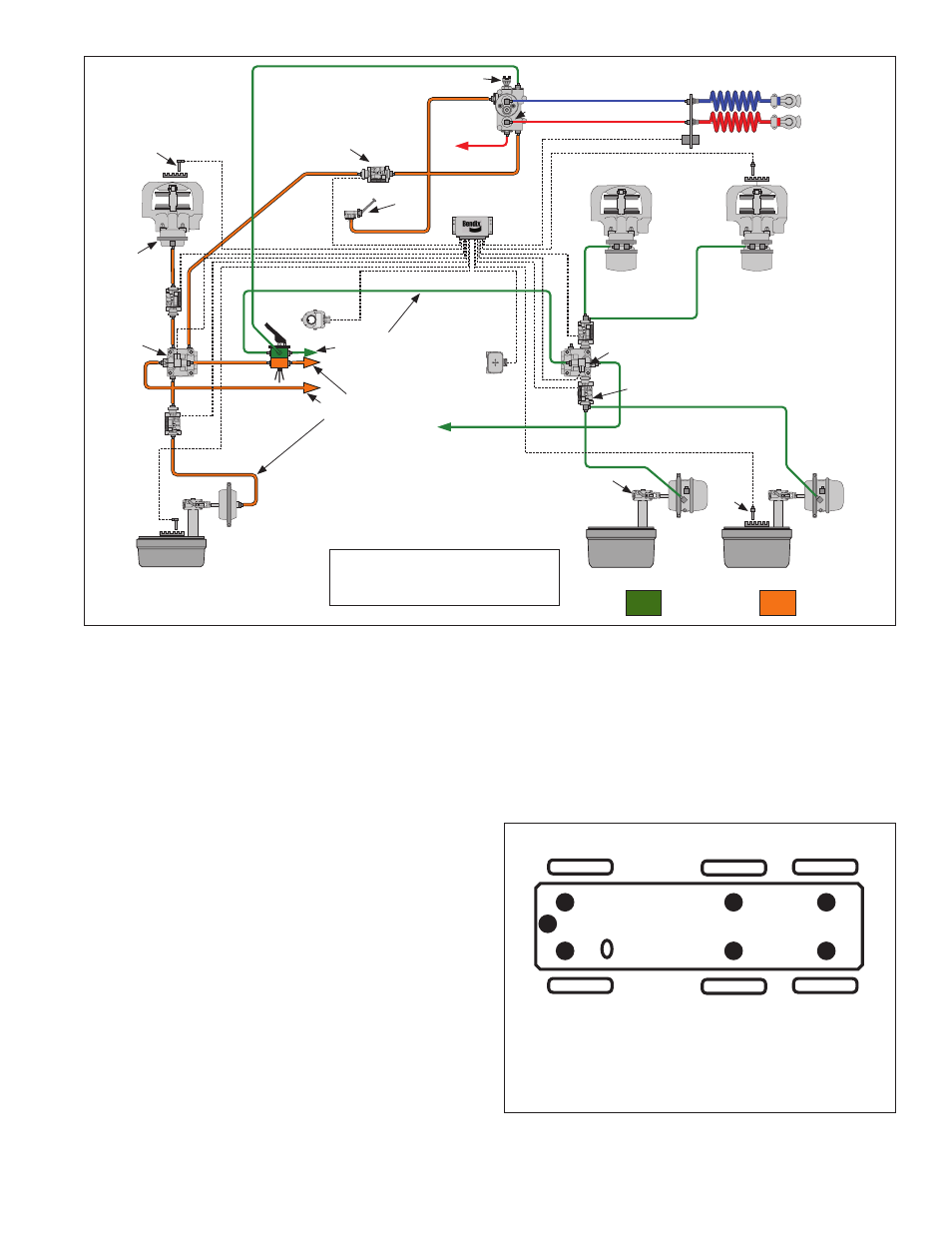
Service & Spring
Brake Chamber
Antilock
Controller
Slack Adjuster
Wheel
Speed
Sensor
Wheel
Speed
Sensor
Wheel
Speed
Sensor
Yaw Rate Sensor
Steering Angle Sensor
Service
Brake
Chamber
Brake Valve
Glad Hands
Spring Brake
Chamber
Service Brake
Chamber
C
S
SL-4
™
Stop Light Switch
TP-5
™
Tractor Protection Valve
TCS-9000
™
Trailer
Control Valve
Pressure
Modulator
Valve
Pressure
Modulator
Valve
Pressure Modulator Valve
Pressure
Modulator
Valve
Pressure Modulator Valve
Antilock Relay Valve
Antilock
Traction
Relay
Valve
Air Disc
Brake
For Illustration Purposes Only, Both Air
Disc Brakes And Foundation Drum Brakes
Are Shown At Either Side Of The Axles.
Air Disc
Brakes
Foundation
Drum Brakes
Foundation
Drum Brakes
Trailer (Supply)
Trailer (Control)
Secondary
Brake Circuit
Secondary
Brake Circuit
Primary Brake
Circuit
Primary Brake
Circuit
FIGURE 4 - TYPICAL SYSTEM DIAGRAM (4S-4M SYSTEM SHOWN)