Brake assembly (continued) – Bendix Commercial Vehicle Systems 16 1/2 SCAM/XTRA LIFE SERV MANUAL User Manual
Page 19
BRAKE ASSEMBLY (CONTINUED)
17
FFFFFigur
igur
igur
igur
igure 1
e 1
e 1
e 1
e 14
4
4
4
4
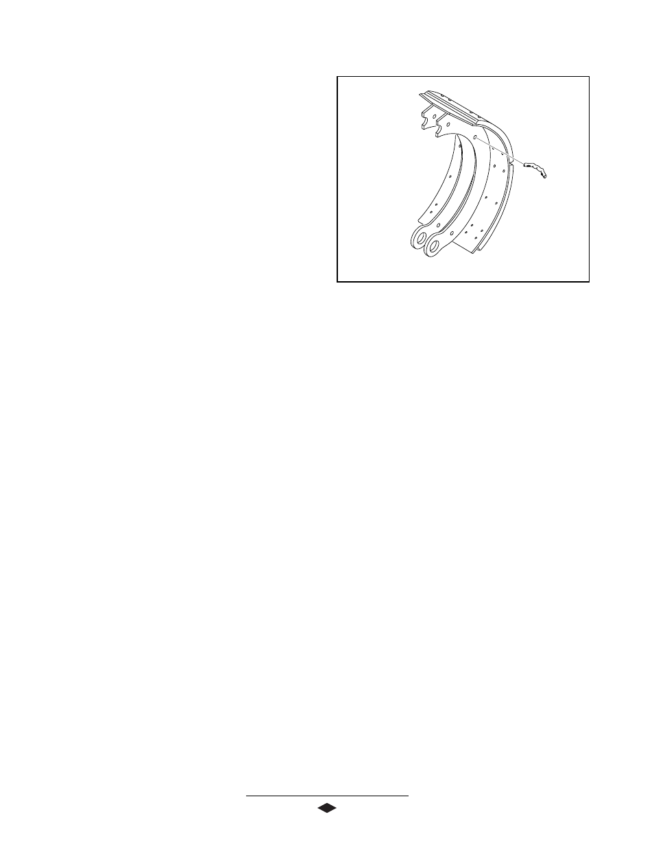
“P” SERIES
1
1
1
1
1.
Install new return spring pins. See F
See F
See F
See F
See Figur
igur
igur
igur
igure 1
e 1
e 1
e 1
e 14.
4.
4.
4.
4.
2.
2.
2.
2.
2.
Align lower end of fabricated shoe with spider bore.
3.
3.
3.
3.
3.
Place snap ring on anchor pin end with grease
fitting. Place thin spacer onto anchor pin.
4.
4.
4.
4.
4.
Install anchor pin through backside of shoe and
spider.
5.
5.
5.
5.
5.
Apply a thin film of Lubriplate 630-A grease or its
equivalent to the anchor pin.
6.
6.
6.
6.
6.
Place thin spacer onto opposite side of anchor pin
and install snap ring.
7
7
7
7
7.....
Hook shoe return spring by pushing shoes to-
gether.
8.
8.
8.
8.
8.
Insert sturdy lever between end of shoe and spider.
Pry shoe away from cam until cam rollers can be
installed. Repeat procedure for opposite side.
SLACK ADJUSTER ASSEMBLY
1.
1.
1.
1.
1.
Reinstall thick camshaft flatwasher.
2.
2.
2.
2.
2.
Install new slack adjuster, shims, and a new snap
ring (In that sequence) into the splined end of the
camshaft.
3.
3.
3.
3.
3.
Adjust camshaft end play of the camshaft to
between .005" and .045" by using the appropriate
number of shims. Make sure the snap ring is seated
into the groove at the end of the splined camshaft.
BRAKE LUBRICATION
1.
1.
1.
1.
1.
Lubricate the camshaft bushings by filling the
camshaft tube with lube through the zerk fitting
provided. Fill until grease is forced out in the area
of the slack adjuster. Grease should not appear at
the cam head end. If it does, the seal has not been
properly installed, or the old seals should be
replaced.
2.
2.
2.
2.
2.
Reinstall brake drums and wheels. Torque and
adjust wheel bearings to manufacturer’s specifica-
tions.
NO
NO
NO
NO
NOTE: Due t
TE: Due t
TE: Due t
TE: Due t
TE: Due to the man
o the man
o the man
o the man
o the many combina
y combina
y combina
y combina
y combinations of slack
tions of slack
tions of slack
tions of slack
tions of slack
adjust
adjust
adjust
adjust
adjuster
er
er
er
ers and br
s and br
s and br
s and br
s and brak
ak
ak
ak
ake chamber
e chamber
e chamber
e chamber
e chambers, follo
s, follo
s, follo
s, follo
s, follow v
w v
w v
w v
w vehicle
ehicle
ehicle
ehicle
ehicle
man
man
man
man
manufactur
ufactur
ufactur
ufactur
ufacturer’
er’
er’
er’
er’s specifica
s specifica
s specifica
s specifica
s specifications and pr
tions and pr
tions and pr
tions and pr
tions and procedur
ocedur
ocedur
ocedur
ocedureeeees for
s for
s for
s for
s for
aaaaassembl
ssembl
ssembl
ssembl
ssembly and final adjustment.
y and final adjustment.
y and final adjustment.
y and final adjustment.
y and final adjustment.
3.
3.
3.
3.
3.
Spin the wheel slowly and adjust the slack adjuster
until wheel will no longer turn. Back off slack
adjuster just enough for wheel to spin freely. Be
sure to adjust brakes equally on each axle.
4.
4.
4.
4.
4.
Apply the release brakes and observe slack adjust-
ers. Both slacks on each axle should respond
rapidly and in unison during application and
release.
5.
5.
5.
5.
5.
Drive vehicle at a low speed in a safe area and
check for brake effectiveness prior to putting back
in service.