Bendix Commercial Vehicle Systems BX2150 AIR COMP (BW1424) User Manual
Page 14
14
TESTING REBUILT COMPRESSOR
In order to properly bench testa compressor under operating
conditions, a test rack for correct mounting, cooling,
lubricating, and driving the compressor is necessary. Such
tests are not compulsory if the unit has been carefully rebuilt
by an experienced person. A compressor efficiency or
build-up test can be run which is not too difficult. The
compressor must be connected to an oil supply line of at
least 15 P.S.I. pressure during the test and an oil return line
must be installed to keep the crankcase drained.
Connect the compressor discharge port to a reservoir with a
volume of 650 cubic inches, including the volume of
connecting line. With the compressor operating at 1800
R.P.M., the time required to raise the reservoir(s) pressure
from 0 P.S.I. to 100 P.S.I. should not exceed 20 seconds.
*During this test, the compressor should be checked for
gasket leakage and noisy operation, as well as unloader
operation and leakage.
*NOTE: With no inlet check valve or air strainer attached to
the compressor inlet.
TABULATED TECHNICAL DATA
Average weight
33 lbs.*
Number of cylinders
1
Bore size
3.375"
Stroke
1.468"
Displacement at 1250 R.P.M.
9.5 C.F.M.
Maximum recommended R.P.M.
3000 R.P.M.
Minimum coolant flow (water cooled) at
Maximum R.P.M.
2.5 G.P.M.
Minimum R.P.M.
.5 G.P.M.
Minimum coolant flow (air-cooled)
N/A
Approximate horsepower required at
1250 R.P.M. at 120 PSIG
(naturally aspirated)
1.7
Turbocharge limits
Maximum R.P.M.
2200 R.P.M.
Maximum pressure (gauge)
15 PSIG
Maximum inlet air temperature
250° F
Maximum discharge air temperature
400° F
Minimum pressure required to unload
(naturally aspirated)
60 PSIG
(with inlet check valve)
85 PSIG
(turbocharged)
85 PSIG
Minimum oil pressure required
at engine idling speed
5 PSIG
Minimum oil pressure required at
any engine speed
15 PSIG
Oil capacity of self-lubricated model
N/A
Minimum discharge-line size
1/2" I.D.
Minimum coolant-line size
3/8" I.D.
Minimum oil-supply line size
3/16" I.D.
Minimum oil-return line size
1/2" I.D.
Minimum air-inlet line size
5/8" I.D.
Minimum unloader-line size
3/16" I.D.
*Installed weight determined by final mounting configuration.
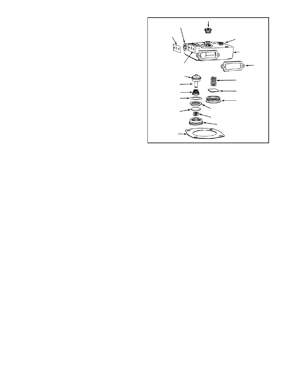
UNLOADER KIT
The unloader kit is designed for use when unloader piston
leakage is detected as described under the Compressor
Air Leakage Tests section of this manual. The kit contains
the following components which are keyed to Figure 12.
Qty.
Description
Key
1
Unloader stop assembly
3
1
Unloader piston assembly
4
MAJOR MAINTENANCE KIT
The major maintenance kit is designed to rebuild the
BX-2150
™
compressor head assembly and contains the
following parts which are keyed to Figure 12.
Qty.
Description
Key
1
Unloader Kit
3 & 4
1
Discharge Valve
12
1
Governor Gasket
1
1
Strainer Gasket
2
1
Discharge Valve Spring
13
1
Cylinder Head Gasket
14
1
Unloader Spring
10
1
Inlet Valve Gasket
9
1
Discharge Valve Seat
11
1
Inlet Valve Stop
5
1
Inlet Valve
7
1
Inlet Valve Seat
8
1
Inlet Valve Spring
6
1
WATER PORT
3
GOVERNOR
MOUNTING PAD
DISCHARGE
PORT
WATER PORT
4
10
9
7
14
5
6
8
13
12
11
2
O-RING
FIGURE 12
14