Bendix Commercial Vehicle Systems BA-921 SMC COMPRESSOR User Manual
Page 10
10
8. Gently tap the cylinder head, cooling plate and valve
plate assembly with a soft mallet to break the gasket
seals. Then separate the cylinder head from the cooling
plate and valve plate assembly and remove the two
gaskets (2) between them.
CRANKCASE FRONT COVER
1. Remove the cover (11) from the front of the crankcase.
Use a sharp fl at head screw driver or a scraper. Place
the edge under the lip along the outside diameter of
the cover. Pry the cover from the cast surface until the
cover can be removed.
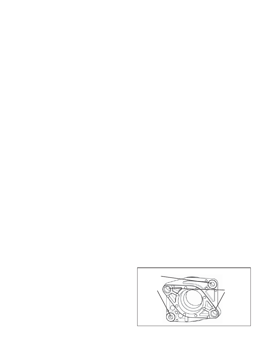
REAR END COVER
1. Note: There are two cap screws used to retain the
end cover to the crankcase. There are two longer cap
screws (not shown in Figure 10) that are used to retain
the auxiliary drive unit (i.e. hydraulic pump) via the end
cover and torqued into the crankcase. If the auxiliary
drive unit has already been removed, these two cap
screws are no longer present on the end cover. Refer
to Figure 9 to see location of the cap screws in the end
cover.
2. Remove the two end cover cap screws that secure the
rear end cover to the crankcase.
3. Remove the rear end cover from the crankcase.
Remove and discard the o-ring (10) from the end cover.
CLEANING OF PARTS
GENERAL
All parts should be cleaned in a good commercial grade of
solvent and dried prior to inspection.
CRANKCASE
1. Carefully remove all sealant gasket material adhering
to the machined face of the crankcase. See Figure
3. Make certain not to scratch or mar the mounting
surface. Note: Keep the crankcase opening covered
to prevent any of the sealant material from entering.
Repeat this process on the engine mounting face as
well. Follow the instructions contained in the vehicle
maintenance manual in lieu of the instructions and
procedures presented in this manual.
2. Carefully remove all gasket material adhering to the
deck (top) of the crankcase. Remove any carbon
deposits from the deck of the crankcase. Make certain
not to scratch or mar the gasket surfaces.
CYLINDER HEAD ASSEMBLY
1. Carefully remove all gasket material adhering to the
cylinder head, cooling plate, valve plate assembly and
cast iron crankcase. Make certain not to scratch or
mar the gasket surfaces. Pay particular attention to
the gasket surfaces of the head.
2. Remove carbon deposits from the discharge and inlet
cavities of the cylinder head, cooling plate and valve
plate assembly. They must be open and clear in both
assemblies. Make certain not to damage the head.
3. Remove rust and scale from the cooling cavities and
passages in the cylinder head, cooling plate and valve
plate assembly and use shop air to clear debris from
the passages.
4. Check the threads in all cylinder head ports for
galling (e.g. abrasion, chafi ng). Minor thread chasing
(damage) is permitted.
5. Remove any carbon or old grease from the two bores
in the unloader cavity of the cylinder head.
INSPECTION OF PARTS
CYLINDER HEAD, COOLING PLATE, VALVE
PLATE ASSEMBLY AND UNLOADER MECHANISM
1. Carefully inspect the head gasket surfaces on the
cylinder head for deep gouges and nicks. Also, inspect
the cylinder head for any cracks or port thread damage.
If detected, the compressor must be replaced. If large
amounts of carbon build-up are present in the discharge
cavity, such that it restricts the air fl ow through the
cylinder head, the compressor should be replaced.
2. Carefully inspect both sides of the head gasket
surfaces on the cooling plate for deep gouges and
nicks. Also, inspect the cooling plate for any cracks
or other damage. If cracks or damage are found, the
compressor must be replaced.
3. Carefully inspect the valve plate assembly gasket
surfaces (both sides) for deep gouges and nicks.
Pay particular attention to the gasket surface. An
inlet reed valve/gasket (1) is used between the valve
plate assembly and crankcase. This gasket surface
must be smooth and free of all but the most minor
scratches. If excessive marring or gouging is detected,
the compressor must be replaced. If large amounts of
carbon build-up are present on the two main surfaces, in
the two discharge valve holes or between the discharge
valve and the discharge seat, the compressor should
be replaced.
FIGURE 10 - REAR END COVER ATTACHMENT BOLTS
M10x1.5
Cap
Screws
(Larger)
M8x1.25
Cap
Screws
(Smaller)