Operational test, If the trailer is equipped with an r-12p, Valve – Bendix Commercial Vehicle Systems TRAILER SYSTEM GUARD AIR DRYER 7/04 User Manual
Page 5
5
2. Connect the supply and control lines to the Trailer
System-Guard
™
air dryer making sure to keep the control
and supply circuits separate as shown. Do not switch
lines end to end. All ports are identified as indicated in
figures 1 and 2.
3. Affix the Alcohol Warning Decal to the trailer bulkhead.
Before applying the decal remove all oil and road
contaminants from the mounting location with a good
cleaning solvent.
OPERATIONAL TEST
Build the air system to governor cutout. Shut off the engine.
Using a soap solution, check all lines and fittings leading
to and from the Trailer System-Guard
™
air dryer for leakage
and integrity. Repair any excessive leaks - exceeding a 1"
bubble in 5 seconds - before restoring vehicle to service.
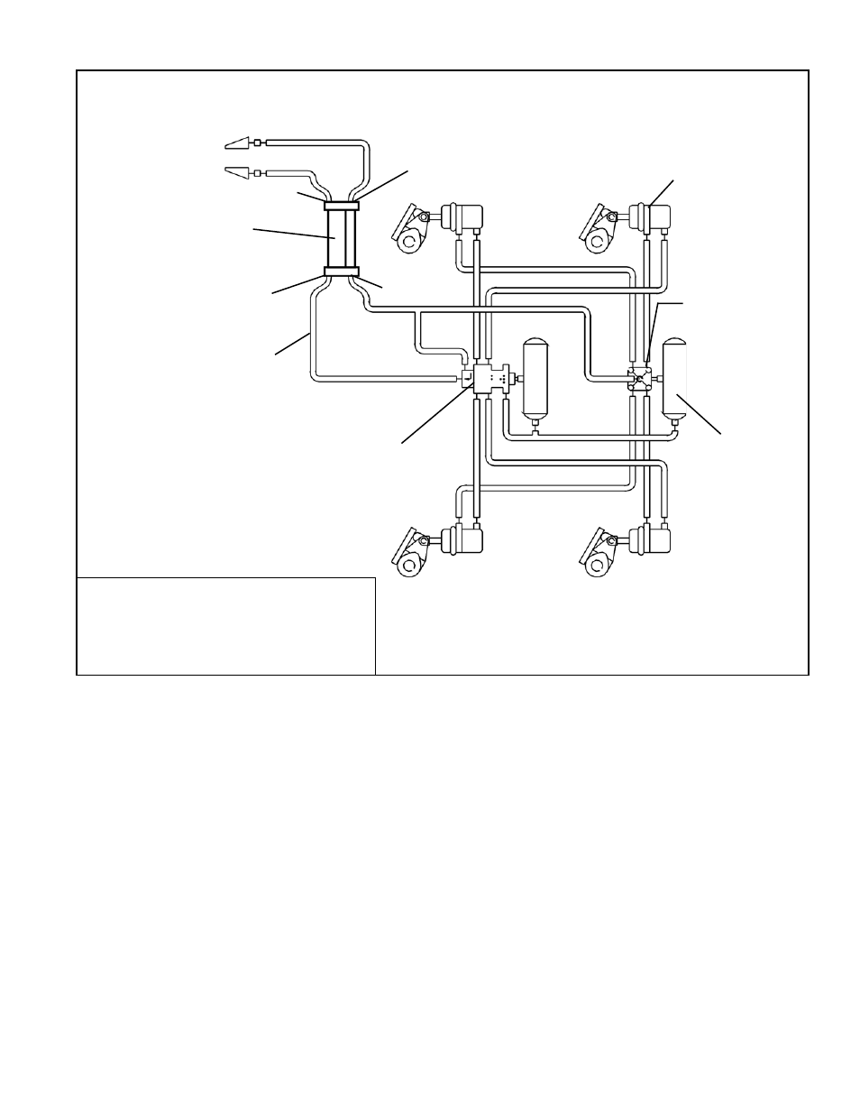
Supply
Trailer
System-Guard
™
Air
Dryer
FIGURE 4 -TRAILER SYSTEM-GUARD
™
AIR DRYER PLACEMENT
"12 IN
SUP"
"11 IN
CONT"
R-12
™
Relay
Valve
Spring
Brake
Valve
Reservoir
"22 OUT
SUP"
"21 OUT
CONT"
Spring
Brake
If the trailer is equipped with an R-12P
™
valve, the trailer systems guard must be
mounted upstream of the R-12P
™
valve.