Bendix Commercial Vehicle Systems DRM DRYER RESERVOIR MODULE 3/07 User Manual
Page 9
9
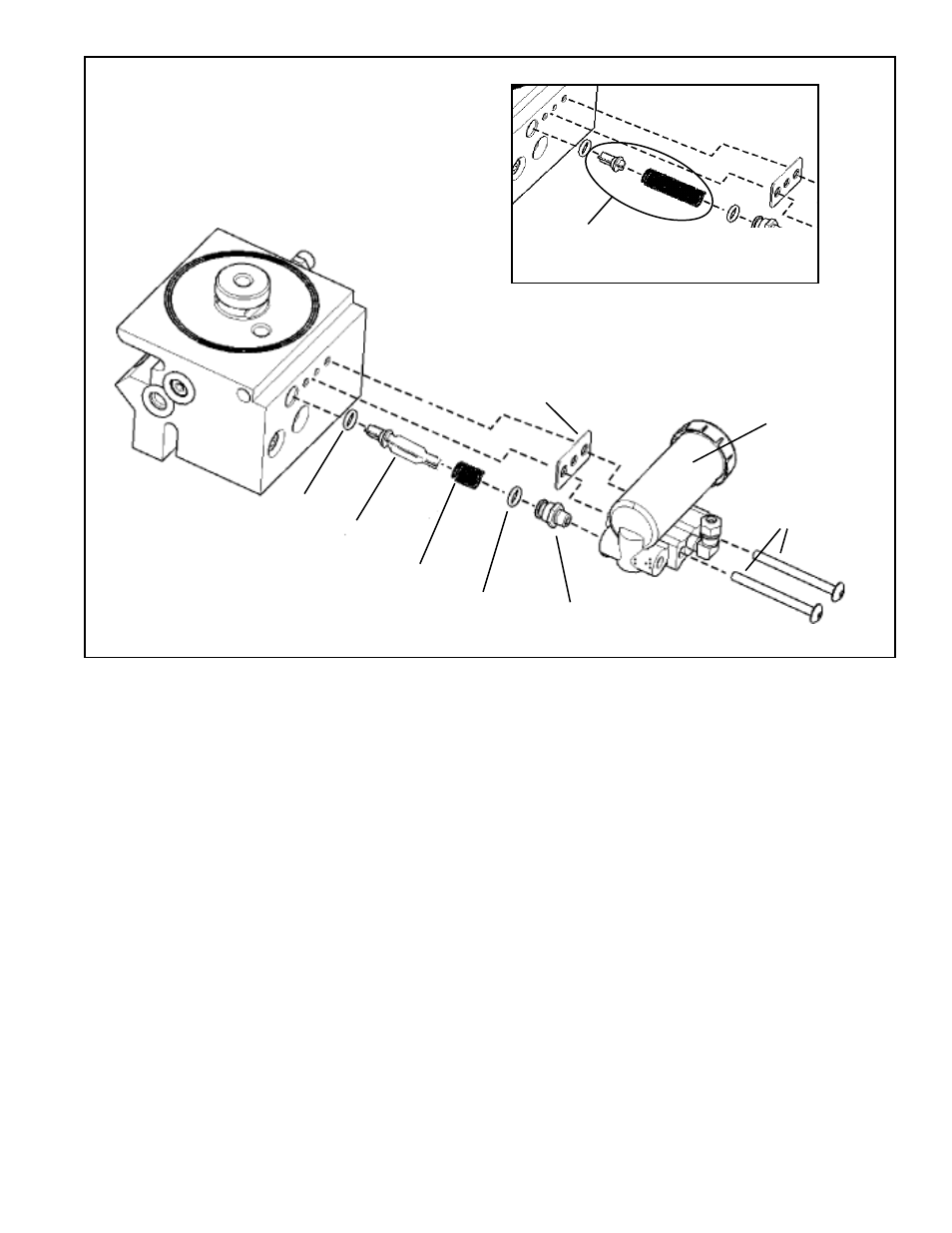
FIGURE 7 - AD-IS
®
AIR DRYER DELIVERY CHECK VALVE
GOVERNOR GASKET
(SPECIAL GASKET,
SEE NOTE 6 ON
PREVIOUS PAGE)
GOVERNOR
(NON-ADJUSTABLE,
130 PSI CUT-OUT)
BOLTS
ADAPTER
LARGE
O-RING
SPRING
CHECK VALVE
BODY
SMALL
O-RING
ORIGINAL STYLE
CHECK VALVE AND
SPRING
Early models include a different style check
valve and spring
ASSEMBLY
1. Lubricate the smaller o-ring and check valve body with
barium or silicon grease.
2. Install this o-ring on the check valve body by sliding the
o-ring over the set of 4 tapered guide lands. The
o-ring groove holds the o-ring in its correct location.
3. At the other end of the check valve body, the spring is
installed over the set of 4 straight guide lands. When
the spring has been pushed to the correct location, the
check valve body is designed to hold the end of the spring
in position - be sure that the spring is not loose before
continuing with this installation.
4. Install the assembled check valve body/o-ring/spring in
the delivery port so that the o-ring rests on its seat and
the free end of the spring is visible.
5. Grease the adapter and the remaining larger o-ring and
install it onto the fitting.
6. Position gasket, insert bolts through the governor and
tighten (to 125 in-lbs). (Note: Do not replace with a
standard compressor/governor gasket.)
7. Reattach line to the governor.
8. Before placing vehicle back into service, check to see
that the system pressure now builds to full operational
pressure.