Bendix Commercial Vehicle Systems EC-17 ANTILOCK TRACTION CONTROL4/10 User Manual
Page 11
11
Separate dash lamps, controlled by the EC-17
™
/EC-17N
™
controller, advise the driver of the condition of the entire
antilock/traction system.
When the controller senses an erroneous condition, it stores
the condition in memory, illuminates the dash mounted
condition lamp and after certain criteria are met it disables
the antilock or traction control function. If so equipped, the
EC-17
™
controller illuminates the appropriate diagnostic
LEDs.
The diagnostic trouble code condition is truly stored and is
not cleared by loss of power to the antilock system. The
optional LEDs will illuminate when power is restored and
remain illuminated until the failure is corrected. After the
actual issue is corrected, maintenance personnel can clear
or reset the EC-17
™
controller diagnostics through the S.A.E.
J1587 diagnostic link or the optional magnetic RESET point
in the diagnostics display. To clear or reset an EC-17N
™
controller (not equipped with LEDs) the S.A.E. J1587
diagnostic link must be utilized.
IMPORTANT:
The balance of this manual deals with diagnostics and
controller self-configuration using the optional LED
display on the EC-17
™
controller (see Figure 1). Antilock
systems using the EC-17N
™
controller (see Figure 1)
must use the Bendix, Diagnostic Communication
Interface or DCI for diagnostics or reconfiguration.
Used with its Microsoft Windows* based software and a
personal computer, the DCI is able to provide the technician
with a high level of diagnostic information and antilock
diagnostic trouble code history. This is particularly useful
when attempting to determine the source of intermittent
diagnostic trouble code indication from the antilock dash
condition lamp.
For field use or when a PC is not available, the DCI’s integral
LED display and switch provides the EC-17N
™
controller
user with exactly the same information that is available from
the optional LED display on the EC-17
™
controller. When
using the DCI’s LED display for system diagnosis or controller
self-configuration the descriptions and procedures presented
* Windows is a registered trademark of Microsoft Corporation.
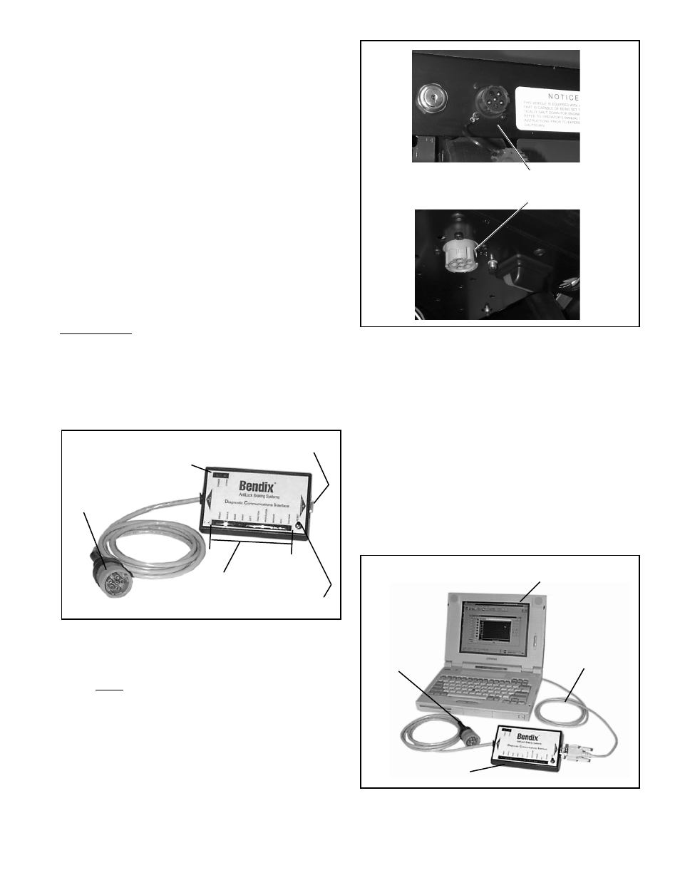
VEHICLE DIAGNOSTIC
CONNECTOR (J1587)
FIGURE 9 VEHICLE DIAGNOSTIC CONNECTOR
LOCATION
DIAGNOSTIC COMMUNICATION INTERFACE
The DCI (part # 5004893) is a dual level electronic diagnostic
tool for either the EC-17
™
or EC-17N
™
antilock controller. It
can either be used as a “stand alone” diagnostic tool or with
Bendix’s ACom For Windows software (part # 5004892).
In order to use the DCI, the vehicle must be equipped with a
J1587 diagnostic link connector as illustrated in Figure 9.
This connector is generally located on the driver’s side, in
lower portion of the dash or under the dash panel.
MPSI Tool: Multi Protocol Cartridge (J38500-1500), PCMCIA
Card For Bendix (J38500-2400).
FIGURE 10 DCI CONNECTED TO LAP TOP COMPUTER
DCI
SERIAL
CABLE
LAP TOP
COMPUTER
TO VEHICLE
J1587
CONNECTOR
DIAGNOSTIC
LAMPS
RESET
SWITCH
COMPUTER
SERIAL PORT
CONNECTOR
J1587
DIAGNOSTIC
CONNECTOR
(CONNECTED
TO VEHICLE)
POWER AND
COMMUNICATION
INDICATION LAMPS
FIGURE 8 DIAGNOSTIC COMMUNICATIONS INTERFACE