Operation, Trailer brake system with r-12p, Pilot relay valve – Bendix Commercial Vehicle Systems R-12P PILOT RELAY VALVE 4/11 User Manual
Page 2
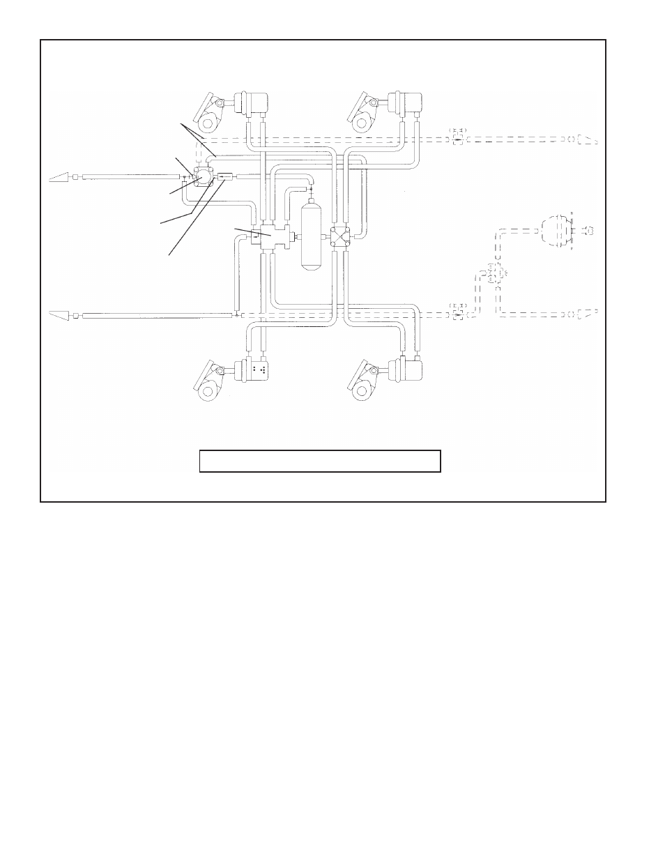
2
FIGURE 2 - TYPICAL R-12P
™
PILOT RELAY VALVE SYSTEM SCHEMATIC
DELIVERY
SPRING
BRAKE
VALVE
SUPPLY
SERVICE RELAY
VALVE
QUICK
RELEASE
VALVE
VENTED
CUT-OUT
COCK
SINGLE
CHECK VALVE
VENTED
CUT-OUT
COCK
RESERVOIR
CONTROL
BRAKE CHAMBER
SLACK ADJUSTER
SUPPLY
CONTROL
R-12P
™
VALVE
OPERATION
CHARGING
When the air brake system is charging, the relay pis ton’s
exhaust seat is against the inlet/exhaust valve due to
the force of the reserve spring. Reservoir air enters the
Bendix
®
R-12P
™
valve supply port and becomes active
upon the inlet/exhaust valve. At the same time, reservoir
air passes through the R-12P
™
valve body channel to the
load piston. Supply air builds simultaneously and equally
underneath the inlet/exhaust valve and above the load
piston. While supply pressure continues to hold the inlet/
TRAILER BRAKE SYSTEM WITH R-12P
™
PILOT RELAY VALVE
exhaust valve against its seat, it also moves the load piston
into contact with the relay piston. However, even though
force is increasing on the relay piston, it does not move the
inlet/exhaust valve. The effective area of the inlet/exhaust
valve is larger than the effec tive area of the load piston.
Therefore, load piston force cannot overcome inlet/exhaust
valve force. So supply air builds to governor cut-out and the
inlet/exhaust valve remains closed. This is the position of
the R-12P
™
valve in normal run mode, as shown in Figure 3.
-- -- -- -- -- ADDITIONAL PLUMBING FOR TOWING TRAILER