Bendix Commercial Vehicle Systems SR-5 TRAILER SPRING BRK VALVE 4/11 User Manual
Page 3
3
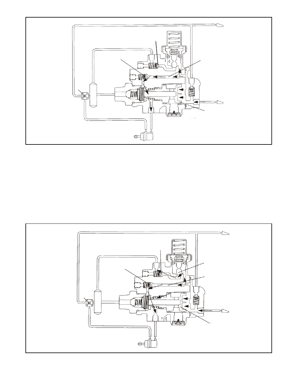
FIGURE 3 CHARGING BELOW 70 PSI
TRAILER SUPPLY
SPRING
BRAKE
CHAMBER
TRAILER SERVICE RES.
CONTROL PISTON
DELIVERY
OPERATION
CHARGING BELOW 70 PSI (SEE FIGURE 3)
Air flows through the trailer supply line, enters the SR-5
™
valve trailer supply port, and moves the control piston. The
control piston contacts the control inlet/exhaust valve,
sealing off the piston’s exhaust passage.
As piston travel continues, the control inlet valve opens. Air
acting on the control piston also flows through passage A,
unseating check valve B, and flowing past the open control
inlet valve. This air flows into the spring brake cavities,
releasing the spring brakes.
CHARGING ABOVE 85 PSI (SEE FIGURE 4)
Air pressure acting on the control piston and flowing through
passage A also acts on pressure protection valve C. At
approximately 85 psi, valve C opens. This allows the air to
flow past check valve D and charge the trailer reservoir(s).
The trailer braking system is now in the normal run mode.
Service braking occurs through the trailer service relay valve.
EXHAUST
PASSAGE A
TRAILER SERVICE
CHECK
VALVE
B
SERVICE/SPRING
BRAKE RESERVOIR
CONNECTION
SERVICE
RELAY
VALVE
CHECK
VALVE
D
FIGURE 4 CHARGING ABOVE 85 PSI
CONTROL PISTON
PRESSURE
PROTECTION
VALVE C
SPRING
BRAKE
CHAMBER
TRAILER SERVICE RES.
EXHAUST
PASSAGE A
TRAILER SERVICE
CHECK
VALVE B
SERVICE/SPRING
BRAKE
RESERVOIR
CONNECTION
SERVICE
RELAY
VALVE
DELIVERY
CHECK
VALVE D