Modulator removal, Modulator installation – Bendix Commercial Vehicle Systems M-12R ANTILOCK MODULATOR User Manual
Page 6
6
8. Use only genuine Bendix
®
replacement parts,
components and kits. Replacement hardware,
tubing, hose, fittings, etc. must be of equivalent
size, type and strength as original equipment and
be designed specifically for such applications and
systems.
9. Components with stripped threads or damaged
parts should be replaced rather than repaired. Do
not attempt repairs requiring machining or welding
unless specifically stated and approved by the
vehicle and component manufacturer.
10. Prior to returning the vehicle to service, make
certain all components and systems are restored
to their proper operating condition.
MODULATOR REMOVAL
1. Identify, mark, or label all air lines and wiring cables and
their respective connections on the modulator (M-12R
™
)
or modulator/controller assembly (M-12
™
).
2. Disconnect all air lines and wiring.
3. Remove the modulator (M-12R
™
) or modulator/controller
assembly (M-12
™
) from the vehicle.
MODULATOR INSTALLATION
1. Install all air line fittings and plugs. Make certain no thread
sealing material enters the modulator.
2. Install the assembled modulator (M-12R
™
) or modulator/
controller assembly (M-12
™
) on the vehicle.
2. Stop the engine and remove ignition key when
working under or around the vehicle. When
working in the engine compartment, the engine
should be shut off and the ignition key should be
removed. Where circumstances require that the
engine be in operation, EXTREME CAUTION should
be used to prevent personal injury resulting from
contact with moving, rotating, leaking, heated or
electrically charged components.
3. Do not attempt to install, remove, disassemble or
assemble a component until you have read and
thoroughly understand the recommended
procedures. Use only the proper tools and observe
all precautions pertaining to use of those tools.
4. If the work is being performed on the vehicle’s air
brake system, or any auxiliary pressurized air
systems, make certain to drain the air pressure from
all reservoirs before beginning ANY work on the
vehicle. If the vehicle is equipped with an AD-IS
™
air dryer system or a dryer reservoir module, be
sure to drain the purge reservoir.
5. Following the vehicle manufacturer’s
recommended procedures, deactivate the electrical
system in a manner that safely removes all
electrical power from the vehicle.
6. Never exceed manufacturer’s recommended
pressures.
7. Never connect or disconnect a hose or line
containing pressure; it may whip. Never remove a
component or plug unless you are certain all
system pressure has been depleted.
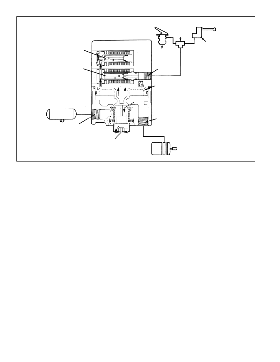
FIGURE 6 ANTILOCK MODE: SOLENOIDS ACTIVATED
DELIVERY
PISTON
EXHAUST
SUPPLY
EXHAUST
SOLENOID
CONTROL
DOUBLE
CHECK
BRAKE
VALVE
SUPPLY
SOLENOID
SERVICE BRAKE
CHAMBER
RESERVOIR
TRAILER
CONTROL