Troubleshooting information, Troubleshooting, Diagnostic display quick reference – Bendix Commercial Vehicle Systems MC-12 MODULATOR CONTROLLER ASSY User Manual
Page 9
9
TROUBLESHOOTING INFORMATION
PREPARATION FOR TESTING
All trailer antilock testing should be performed with a tractor
connected to the trailer.
1. Connect the tractor to the trailer and build up the air
system, on both the tractor and trailer, to governor cut
out pressure.
2. Park the combination on a level surface. Apply the tractor
parking brakes then release the trailer parking brakes
only and turn off the engine.
NOTE: Some tractors may not have the ability to release
the trailer brakes while the tractor parking brakes remain
applied. In this event, chock all wheels, build the tractor
and trailer system to governor cut out and turn off the
engine without applying the parking brakes.
TROUBLESHOOTING
GENERAL
While the EC-12
™
controller diagnostic display locates a
specific problem area, it is still necessary to confirm whether
the problem resides in the component itself or the wiring.
Basically the troubleshooting procedure that follows is
devoted to narrowing the problem to either the wiring or a
specific antilock component. It should be noted that ALL
TROUBLESHOOTING BEGINS BY OBSERVING THE
ANTILOCK STATUS LAMP ON THE TRAILER WHILE
PERFORMING THE "INITIAL START-UP PROCEDURE" and
following the directions contained in the procedure.
Be sure to record a failure before resetting the system. Reset
by holding a magnet (capable of picking up 3 ounces) over
the reset location on the diagnostic window. If the LED(s) do
not clear during a reset, check all wiring and hardware per
the troubleshooting chart (BWS 1082). During a reset, all
LEDs will illuminate until the magnet is removed.
IMPORTANT - TROUBLESHOOTING TIPS
1. Record all findings and the action taken during the
troubleshooting process. The record sheet should be
filed in the trailer maintenance folder for future reference
and comparison.
2. No voltage or resistance tests are performed into the
EC-12
™
controller. All voltage and resistance tests are
performed by beginning at the wire harness half of the
connector and moving AWAY from the EC-12
™
control-
ler toward an antilock system component (modulator,
wheel speed sensor, etc.)
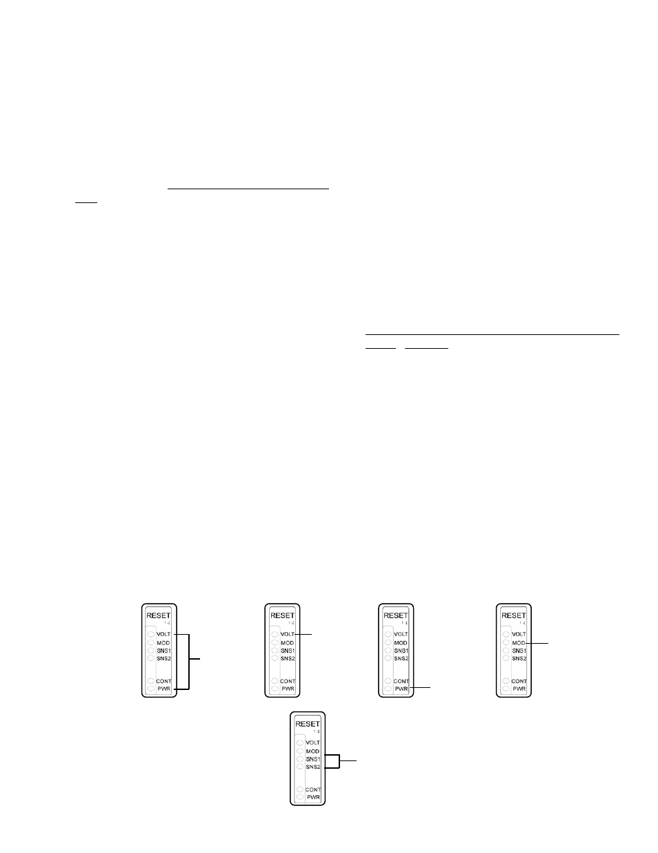
NOTHING ON
GO TO
SECTION IV
GO TO
SECTION IV
NOT ON
GO
TO SECTION IV
ONE OR BOTH ON
GO TO SECTION VIA
ON
GO TO
SECTION V
DIAGNOSTIC DISPLAY
QUICK REFERENCE
This index is presented for the benefit of personnel experienced in troubleshooting Bendix
®
MC-12
™
trailer antilock
system. It provides a quick reference to specific sections that provide testing procedures and values.