Bendix Commercial Vehicle Systems SR-1 SPRING BRAKE VALVE User Manual
Page 4
4
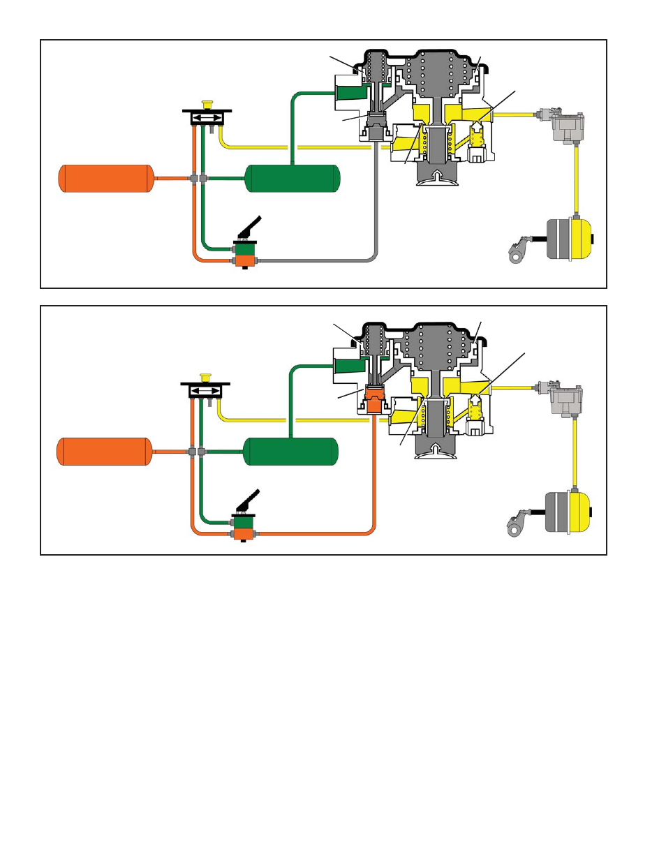
FIGURE 7 - NORMAL SERVICE APPLICATION
FIGURE 6 - PARKING BRAKE SUPPLY DELIVERY EQUAL TO OR GREATER THAN 95 P.S.I.
*Note: Other spring brake hold-off pressures are
supplied according to the vehicle manufacturer’s
specifi cations. 95 P.S.I. was chosen only for the
purpose of explanation.
OPERATION - NORMAL SERVICE RESERVOIRS
1 & 2 CHARGED
When a service application is made by actuating the dual
brake valve, air from the No. 2 delivery circuit is delivered
from the brake valve to the control port, and is stopped at
the closed inlet of valve A. No movement of the internal
components of the Bendix
®
SR-1
™
valve takes place.
Air from the No. 1 delivery circuit of the dual brake valve
actuates the service section of the spring brake actuators.
Refer to Figure 7.
OPERATION - SERVICE APPLICATION WITH LOSS
OF NO. 2 RESERVOIR PRESSURE
In the event air pressure is lost in the No. 2 reservoir,
the No. 1 reservoir and the parking control valve will be
protected via the double and single check valves in the
air system. A service application of the foot brake valve
in this situation results in little or no air being delivered
from the No. 2 delivery circuit to the control port of the
SR-1 valve. No movement of the SR-1 valve internal
components takes place. Braking is assured because the
No. 1 service reservoir is protected by a check valve and
the No. 1 delivery circuit of the dual brake valve will apply
the service section of the spring brake actuators.
#2 SERVICE
RESERVOIR
#1 SERVICE
RESERVOIR
DOUBLE
CHECK
VALVE
PISTON B
CHECK VALVE
INLET &
EXHAUST A
PISTON A
INLET
&
EXHAUST
B
EXHAUST
SPRING
BRAKE
#2 SERVICE
RESERVOIR
#1 SERVICE
RESERVOIR
DOUBLE
CHECK
VALVE
PISTON B
CHECK VALVE
INLET &
EXHAUST A
PISTON A
INLET
&
EXHAUST
B
EXHAUST
SPRING
BRAKE
BRAKE
VALVE
BRAKE
VALVE
R-14
®
RELAY
VALVE
R-14
®
RELAY
VALVE
PARK
CONTROL
VALVE
PARK
CONTROL
VALVE