Bendix Commercial Vehicle Systems TC-2 TRAILER CONTROL BRAKE VALVE User Manual
Page 3
3
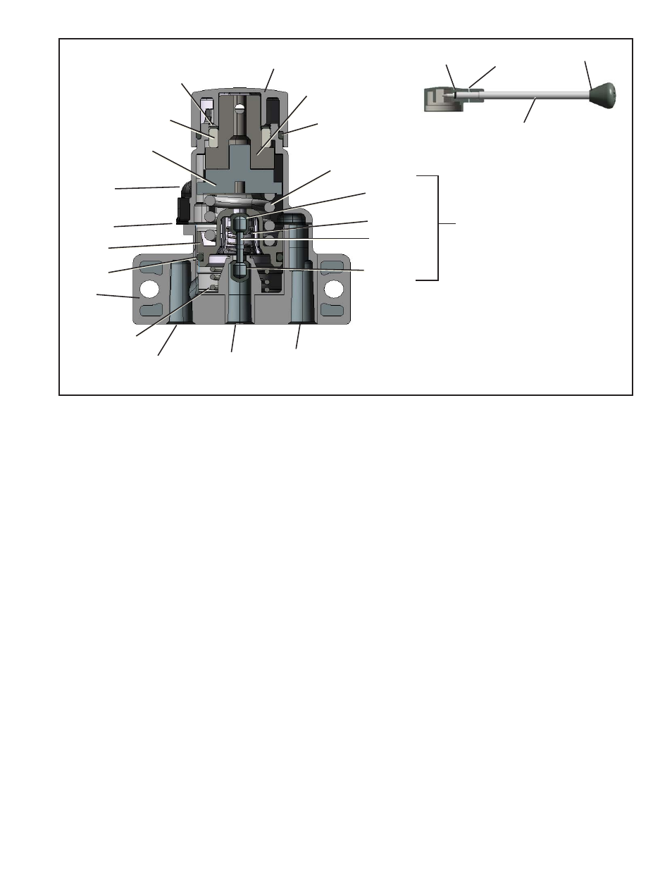
Adjusting Ring
Adjusting Ring
Lock Washer
Head
O-Ring
Cam Follower
Graduating Spring
Inlet Valve
Exhaust
Port
Supply
Port
Delivery
Port
O-Ring
Cam
Gasket
Piston
Piston
Return Spring
Body
Stem
Spring
Exhaust
Valve
TC-2
™
Brake
Valve Insert
O-Ring
Spiral Pin
Handle
Knob
Head
FIGURE 3 - BENDIX
®
TC-2
™
SECTIONAL VIEW
9. Remove the piston and piston return spring from the
body.
10. Remove the piston o-ring.
11. Remove the inlet and exhaust insert screws and lock
washers, then the insert and o-ring seal.
12. The inlet and exhaust valve insert can be disassembled
if desired or necessary.
13. Insert an object, such as a cap screw, in the supply port
to hold the inlet valve on its seat.
14. Depress the exhaust valve guide and spring; remove
the exhaust valve.
15. Remove the stem with inlet valve from the inlet seat
and remove the inlet valve from the stem.
CLEANING AND INSPECTION OF PARTS
1. Clean all metal parts in mineral spirits.
2. Wipe all rubber parts clean.
3. Inspect the valve seats for nicks or burrs.
4. Check all springs for distortion, cracks, and corrosion.
5. All rubber parts should be inspected for wear or
deterioration.
6. Replace all parts not considered serviceable, during
their inspection, with genuine Bendix replacement
parts. Refer to the Quick Reference Catalog (BW1114)
for service parts and kits. To order or download this
catalog visit the Bendix website at www.bendix.com.
ASSEMBLY
Prior to assembly, lubricate the body and cover bores, cam
and cam follower, piston o-ring, and cover top with Dow
Corning
®
55-M pneumatic grease (Bendix piece number
291126).
1. Press the inlet valve on the stem. A little water in the
boot valve or some soap on the stem will make it easier
to press on the inlet valve.
2. Place the stem with the inlet valve installed in the inlet
seat. Insert an object, such as a cap screw, to hold the
inlet valve up against its seat.
3. Position the spring and the exhaust valve guide.
4. Depress the guide and spring, then press the exhaust
valve on the stem.
5. Place the seal o-ring over the insert seat and – with
the cap screws and lock washers – install the inlet and
exhaust insert in the body. The recommended torque
on the insert cap screws is 60 to 80 inch pounds.
6. Install the piston return spring.
7. Install the piston o-ring on the piston and install the
piston in the body.
8. Install the adjusting ring in the cover and screw it down
until it is fl ush with the top of the cover.
9. Place the cam follower and cam in the cover.
10. Position the graduating spring and gasket in the body.
Cover