Bendix Commercial Vehicle Systems BRAKE CHAMBERS User Manual
Page 3
3
When the brake chamber is used to actuate cam-type
foundation brake assemblies, the yoke is connected to
a slack adjuster, which in turn is connected to the brake
cam shaft. This forward motion of the push rod rotates the
slack adjuster, and cam shaft, applying the vehicle brakes.
The greater the air pressure admitted to the brake chamber,
the greater the force applied by the push rod. Conversely,
the less pressure applied to the brake chamber, the less
force will be applied by the push rod. Push rod force is
determined by multiplying the delivered air pressure by the
effective diaphragm area. For example, if 60 psi is admitted
to a type 30 brake chamber, the lineal force on the end of
the push rod is approximately 1800 lbs.
When air pressure is released from the brake chamber,
the push rod return spring — in combination with the brake
shoe return spring — returns the diaphragm, push plate
and rod assembly, slack adjuster, and brake cam to their
released positions, releasing the brakes.
PREVENTIVE MAINTENANCE
A. Each month, every 8,000 miles or every 300 operating
hours, depending on type of operation:
1. Check the push rod to slack adjuster alignment
from release to the full stroke position to be sure
the push rod moves out and returns properly without
binding at the non-pressure plate hole or with other
structures.
Also check the angle formed by the slack adjuster
arm and push rod. It should be greater than 90
0
when the chamber is in the released position and
approach 90
0
at maximum re-adjustment stroke.
2. Check tightness of mounting nuts. Check cotter pins
to make sure they are in place.
3. Check all hoses and lines. They should be secure
and in good condition.
B. Every year, or after each 100,000 miles/3600 oper ating
hours, depending on the type of operation:
1. Disassemble and clean all parts.
2. Install a new diaphragm or any other parts if they are
worn or deteriorated. When the diaphragm, spring,
or both are replaced, they should be replaced in the
corresponding chamber on the same axle.
OPERATING AND LEAKAGE TESTS
A. OPERATING TEST
1. Apply the brakes and observe the push rods move
out promptly and without binding.
2. Release the brakes and observe that the push rods
return to the released position promptly and without
binding.
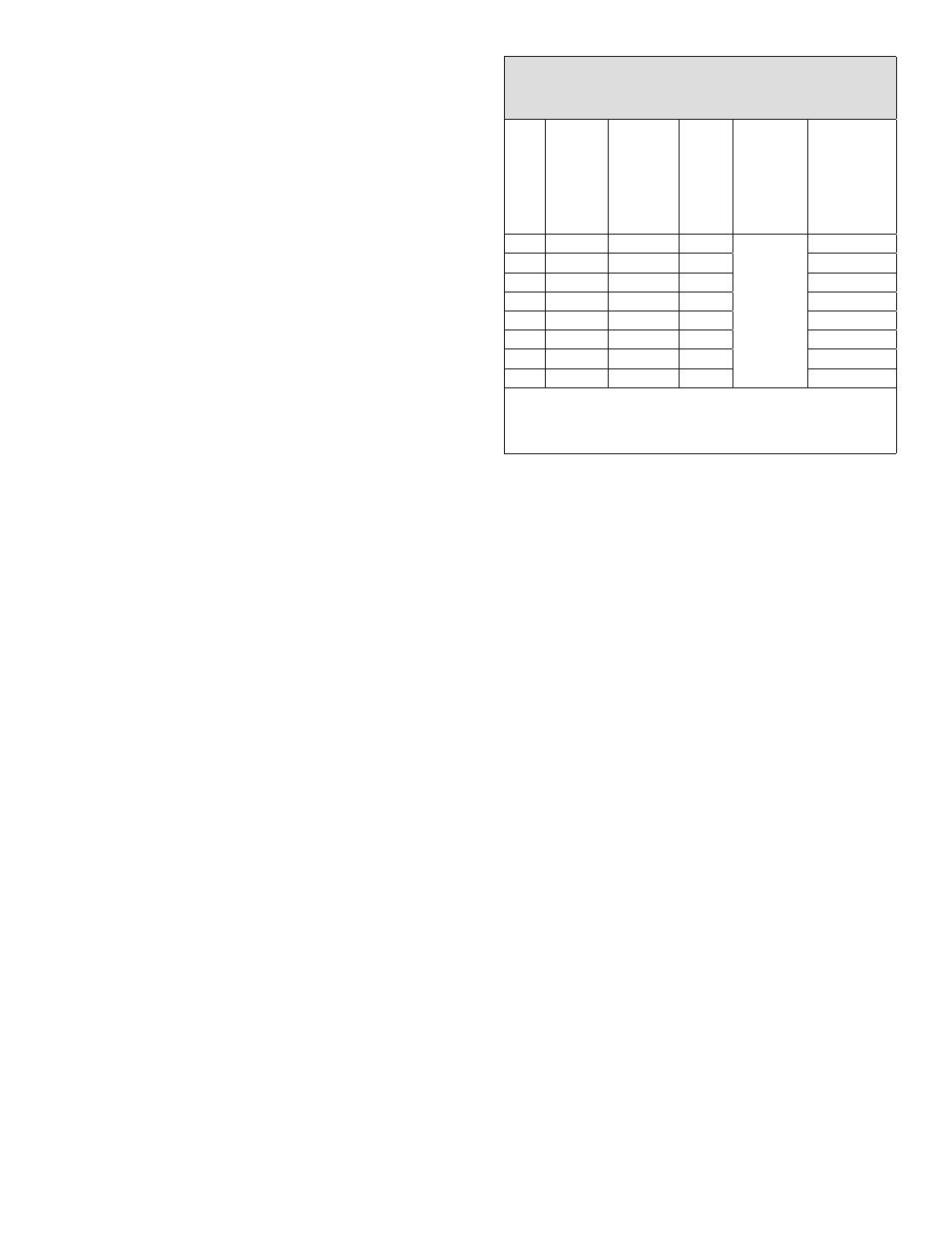
CLAMP-RING TYPE BRAKE CHAMBER DATA
(Dimensions in Inches)
Type
Effective
Area
(Sq. In.)
Outside
Diameter*
Max.
Stroke
Max.
Stroke
With
Brakes
Adjusted
Max. Stroke
at Which
Brakes
Should Be
Readjusted
6
6
4-1/2
1-5/8
Should
be as
short as
possible
without
brakes
dragging
1-1/4
9
9
5-1/4
1-3/4
1-3/8
12
12
5-11/16
1-3/4
1-3/8
16
16
6-3/8
2-1/4
1-3/4
20
20
6-25/32
2-1/4
1-3/4
24
24
7-7/32
2-1/4
1-3/4
30
30
8-3/32
2-1/2
2
36
36
9-5/16
3
2-1/4
*Dimensions listed do not include capscrew head
projections for rotochambers and bolt projections for
clamp-type brake chambers.
FIGURE 3 - DIMENSION CHART
B. LEAKAGE TEST
1. Make and hold a full brake application.
2. Using a soap solution, coat the clamping ring(s). If
leakage is detected, tighten the clamping ring only
enough to stop leakage. DO NOT OVERTIGHTEN
as this can distort the sealing surface or clamping
ring. Coat the area around the push rod hole (loosen
the boot if necessary). No leakage is permitted.
If leakage is detected, the diaphragm must be
replaced.
REMOVING AND INSTALLING
A. REMOVING
1. Block the vehicle wheels.
2. Release the air pressure in all reservoirs.
3. Disconnect the line to the chamber.
4. Remove the yoke pin.
5. Remove the brake chamber.
B. INSTALLING
1. Mount the brake chamber to the mounting bracket.
2. Install the yoke (if removed) and yoke pin.
3. Check the angle formed by the centerline of the push
rod and slack adjuster. Consult the slack adjuster
manufacturer for proper installation angle(s).
4. Connect the line to the chamber. Check to be sure
that the hoses are properly supported and clamped,
if necessary, to provide proper clearance.
5. Adjust the brakes to the slack adjuster manufacturer’s
recommendations.