Warning – Baumfolder BAUM20: Pile Folder 1st Station (from 1999 thru 2001) User Manual
Page 35
PAGE 35 TP10243-1
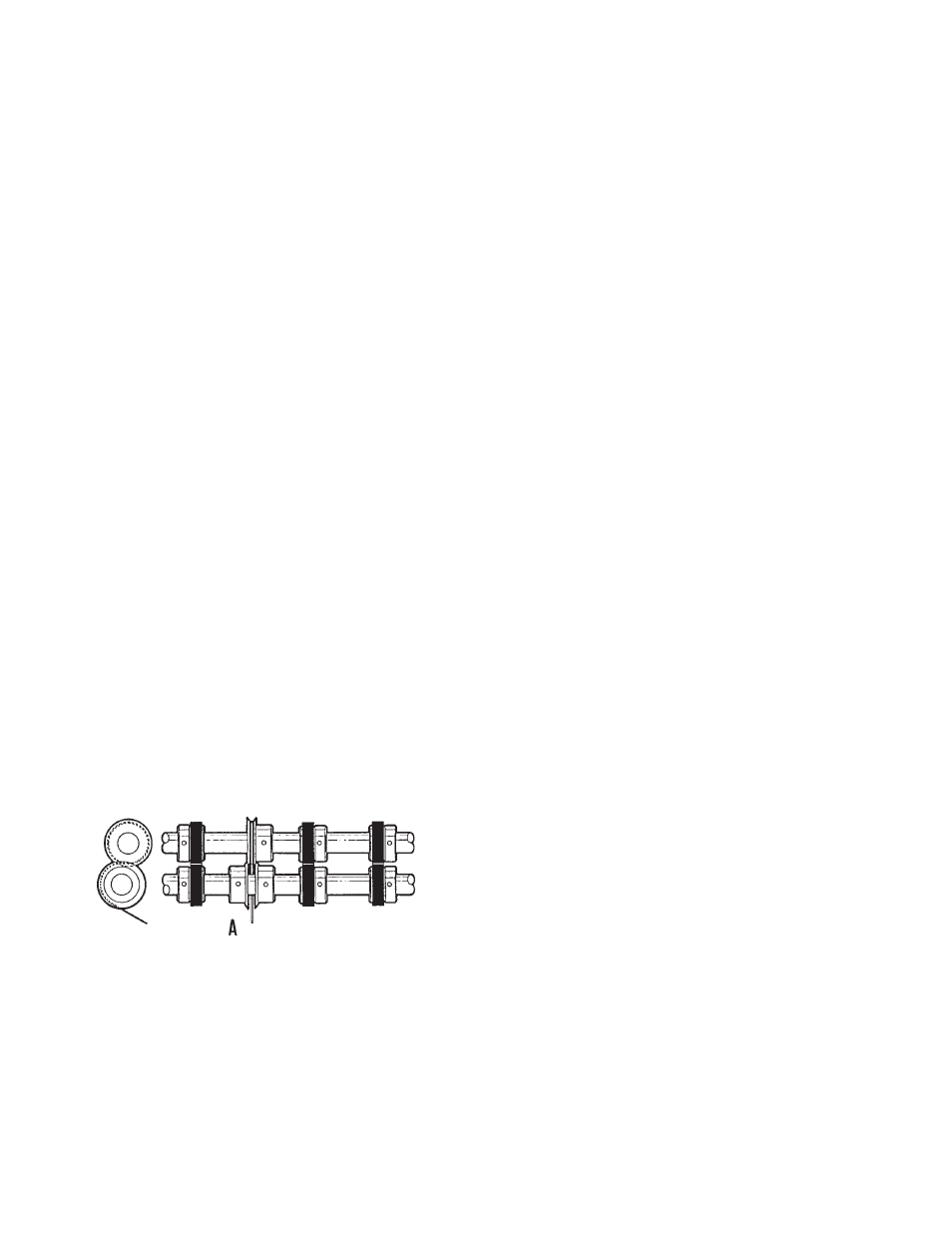
1.5 Trimming a Strip from Center of Sheet
Figure 34 shows the setup for taking a quarter inch trim
out of the center of a sheet. Two or more trims may be made
as long as duplicate sets of cutters and strippers are used
and this setup adhered to.
A strip three sixteenths of an inch wide is the minimum
trim. This is the thickness of two of the cutting blades
placed together and attached to a blade holder collar. Blades
on the upper shaft, for all trims up to one-quarter inch, are
attached to one collar. If a strip wider than one-quarter of an
inch is to be cut, each blade is attached to an individual
collar and any desired width may be cut.
To remove the trim, place the appropriate center stripper
between two of the cutting blades, attached to a collar, as
shown in Figure 34A.
Attaching blades to collars is very important and should
be done with care. The bevel of the cutting blades on the top
shaft should always be directed toward the strip to be
trimmed. The bevel of the blades on the lower shaft should
be directed away from the strip.
Before the cutting blades are tightened to the blade
holder collars, slide both the collar and attached blade on
the end of the shaft so that they are accurately aligned. Place
cutting blades on the upper shaft to the proper position
where the cut is to be made. Then place collars on the lower
shaft so that the flat sides of the blades are pressed snugly
together. Too much space between the blades will give a
ragged edge. Always examine blades for dullness and nicks
which will cause the same condition.
When blades are in the proper position, mount the
stripper as shown. Be sure the stripper does not touch the
sides of the cutting blades.
With this setup, the trimmed out section automatically
goes between the blades on the lower shaft, where it is
carried down and around and guided to the floor by the
stripper wire.
Figure 34
1.6 Blade Installation
WARNING!!!
EXTREME CARE MUST BE TAKEN IN THE
REMOVAL AND INSTALLATION OF ALL
SLITTER, PERFORATING, AND SCORING
BLADES. EXCESSIVE FORCE AND/OR
MISUSE CAN CAUSE PERSONAL INJURY,
BREAKAGE, EQUIPMENT AND MACHINE
DAMAGE
All blade attachment is performed in the same manner.
The locking collar of the blade holder is removed using the
provided spanner wrench.
The blade to be changed is moved far enough along the
slitter shaft to permit the blade to be twisted open and
slipped from the shaft via the slit in the blade.
Install the new blade in the reverse order. Twist the
blade so that the slit opens. Slip the blade onto the slitter
shaft, replace and tighten the locking collar with the
furnished spanner wrench.