Specifications – Bush Hog RTN User Manual
Page 9
RTNR60
RTNR72
RTNR80
Model No.
RTN60
RTN72
RTN80
RTH60
RTH72
RTH80
RTH88
Tillage Width
60”
72”
80’
60”
72”
80”
88”
Number of Blades
28
36
40
28
36
40
44
Type Blades
C-Type
C-Type
C-Type
C-Type
C-Type
C-Type
C-Type
Weight
664 lbs.
726 lbs.
777 lbs.
810 lbs.
884 lbs.
924 lbs.
964 lbs.
No. of Flanges
7
9
10
7
9
10
11
Rotor Speed
238 RPM @ 540 RPM 213 RPM @ 540 RPM
Depth of Cut 7” Adjustable with 5-Position Skid 7” Adjustable
Power to Rotor
Chain Drive (#100) Single Speed Gear Drive
SPECIFICATIONS
2-1 ATTACHING TO TRACTOR
NOTE
The RTN series tiller may be offset to either side if
so desired. Instructions for offsetting are given in
paragraph 2-3.
A. Attach tiller to tractor 3-point hitch per tractor
operator’s manual. Do not attach driveline at this
time.
NOTE
Due to the many variations in tractor/implement hitch
points and corresponding differences in distances
between tractor PTO shafts and implement input
shafts, drivelines may need to be shortened as
described in the following steps:
B. Raise and lower tiller to determine position
with shortest distance between the tractor PTO shaft
and gearbox input shaft. Shut down tractor, leaving
tiller in position of shortest distance. Securely block
tiller in position.
C. Pull driveline apart. Attach outer (female) sec-
tion to tractor PTO shaft. Pull on driveline section to
be sure that yoke locks into place.
D. Hold driveline sections parallel to each other
to determine if it is too long. Each section should end
WARNING
TO AVOID SERIOUS INJURY OR DEATH:
NEVER STAND BETWEEN TRACTOR
AND TILLER WHILE TRACTOR IS BEING
BACKED TO HITCH.
WARNING
TO AVOID SERIOUS INJURY OR DEATH:
ADDITIONAL TRACTOR FRONT BAL-
LAST MAY BE NEEDED FOR STABLE
OPERATION AND TRANSPORT OF THE
TILLER. SEE TRACTOR OPERATOR’S
MANUAL FOR RECOMMENDED WEIGHTS.
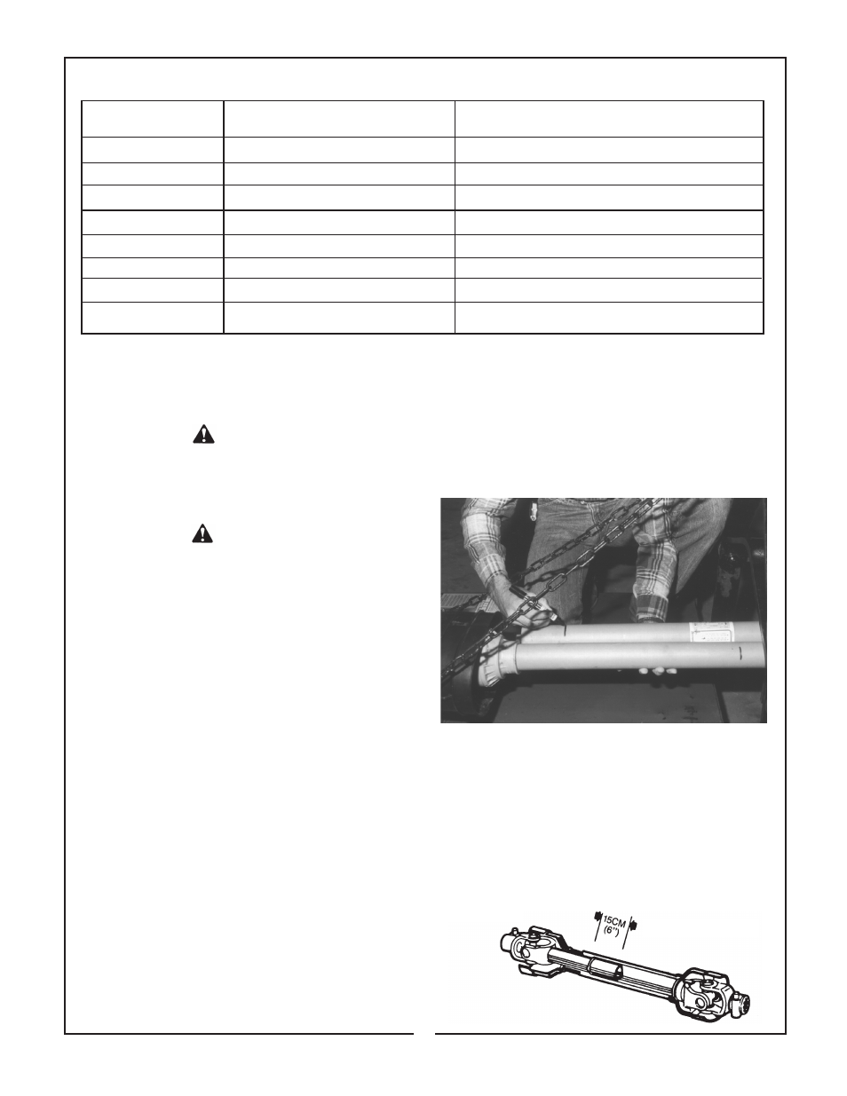
approximately 3 inches (76mm) short of reaching
universal joint shield on opposite section. If too long,
measure 3 inches back from universal joint shield
and mark on opposite section. (Figure 2-1). Do this
for both sections.
Figure 2-1
E. Raise and lower tiller to determine position
with greatest distance between PTO shaft and gear-
box input shaft. Shut down tractor leaving tiller in
position of greatest distance. Securely block tiller
in position.
F. Hold driveline sections parallel to each other
and check for minimum 6 inches (15cm) overlap.
(Figure 2-2) If driveline has been marked for cutting,
overlap will be the distance between two marks. If
driveline has less than minimum overlap, do not use.
Contact authorized Bush Hog dealer.
Figure 2-2
Minimum Overlap
7
SECTION II
PREPARATION FOR USE