B&D Mfg Multizone User Manual
Page 2
The recommended piping schematic is usable with all types of closed-loop, ground source heat pump systems, vertical
bore holes, horizontal loops, slinky, outside headers or inside headers. This recommended method allows for isolating
the heat pump or the loop field for separate flushing and purging. Additionally, the flow through the loops can be
reversed, which may be required when using external headers.
NOTE: The Multizone Flow Centers are designed to work with one common loop field. More than one
flow center on a common loop field will not work properly.
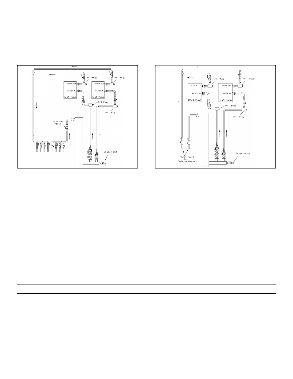
Fig. 4 Illustrates a recommended piping schematic that can be utilized when an internal header is used and separate
purging of the heat pump and the ground loop is not required.
NOTE: Loops should not contain any dirt or debris prior to connecting to the flow center.
Fig. 5 Illustrates a recommended piping schematic for a system with underground headers.
Provide ball valves and P/T ports where indicated. Ball valves shall be the same as pipe size or greater. The flow
center should be fastened to the wall with the bracket provided and all piping should be adequately supported.
All piping shall be properly sized for the flow rate (GPM) required by the system. Reduce pipe size only at flow
center and heat pump as necessary to make connections.
PROCEDURE 1—FILL AND FLUSH A NEW SYSTEM
NOTE: Incorrect piping may not eliminate the air pockets.
1. It is recommended that the loop field is filled, flushed and purged with a flush cart.
NOTE: Properly isolate the flow center with a valve before and after the canister prior to flushing and
purging the loop field.
2
Fig. 4. Recommended Schematic (For Use With
Internal Headers)
Fig. 5. Recommended Schematic (For Use with
Underground Headers; Flush Cart Required)
INSTALLATION
The Multizone is designed to work with up to four heat pumps or four heat pump circuits. Each pumping circuit shall be
checked with the performance curves (See Fig. 1,2 & 3). To ensure adequate flow, the selection must be based on your
specific system design.
The flow center must be located between the heat pump and the ground source system heat exchanger. Location should
be selected on the basis of ease of installation and future service. The flow center is used for filling, flushing, air
elimination, adding anti-freeze and operating the system. This flow center should never be pressurized.